When I reverse multiple elements in a zmx file that was the worst case MC runs, most of the materials disappear.
When I reversed just one element, it did not erase the material. And I have been reversing standard design files (vs MC file which has many coordinate breaks, and the material has offsets). Has anyone else had this issue? Is there a workaround?
Best answer by MichaelH
Hi Sandy,
Can you share your original ZMX file which is failing?
I’ve noticed in the past that surface pickups & virtual propagation (negative thickness in “normal” space or positive thickness in “mirror” space) causes errors with the Reverse Elements tool. I’ve had the best experience when I’ve reversed a system without:
**surface pickups
**virtual propagation
multiple configs
dummy surfaces
“Sag Only” surfaces
** these 2 are the biggest issues I’ve found in the past
When dealing with MC files, there are several pickups, virtual propagations, and coordinate breaks which will probably break the Reverse Elements tool.
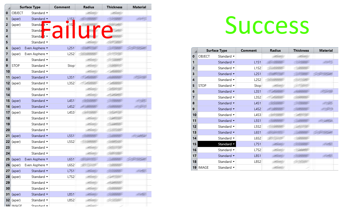
I’ve recently had to reverse a system with dummy surfaces/virtual propagation and ran into issues. For systems with dummy surfaces/virtual propagation, I had to remove the extra surfaces so it’s a “forward only” propagation and “sag only” system:
I use the following workflow to make sure the system is forward/sag only:
Set L1S1 as the GCRS (Global Coordinate Reference Surface)
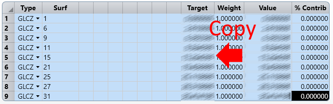
Determine the Global Vertex of the actual surfaces (GLCZ for axially symmetric systems) before removing dummy surfaces
[1, 2, 6, 7, 9, 11, 12, 15, 16, 17, 21, 22, 25, 26, 27, 28, 31, 32] (bold values are the front vertices which will change as dummy surfaces are removed)
Refresh the MFE to get the Value column
Copy the Value column to the Target column
Set the Weight column to 1
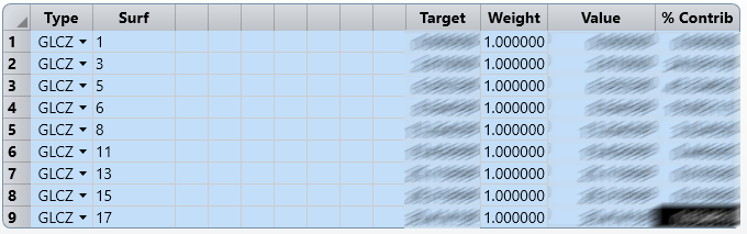
Remove the dummy surfaces so you only have Sag Only surfaces
[1, 2, 3, 4, 5, 6, 7, 8, 9, 10, 11, 12, 13, 14, 15, 16, 17, 18] (bold values are variable air-space thicknesses which can be optimized to the original values)
The Surf column of the GLCZ will automatically update once you remove the dummy surfaces
Make the air-space values a variable
There should only be 1 air-space between lenses now
Re-optimize the system to the original vertex points
This technique produces a valid Reversed System for a traditional imaging system.
Can you share your original ZMX file which is failing?
I’ve noticed in the past that surface pickups & virtual propagation (negative thickness in “normal” space or positive thickness in “mirror” space) causes errors with the Reverse Elements tool. I’ve had the best experience when I’ve reversed a system without:
**surface pickups
**virtual propagation
multiple configs
dummy surfaces
“Sag Only” surfaces
** these 2 are the biggest issues I’ve found in the past
When dealing with MC files, there are several pickups, virtual propagations, and coordinate breaks which will probably break the Reverse Elements tool.
I’ve recently had to reverse a system with dummy surfaces/virtual propagation and ran into issues. For systems with dummy surfaces/virtual propagation, I had to remove the extra surfaces so it’s a “forward only” propagation and “sag only” system:
I use the following workflow to make sure the system is forward/sag only:
Set L1S1 as the GCRS (Global Coordinate Reference Surface)
Determine the Global Vertex of the actual surfaces (GLCZ for axially symmetric systems) before removing dummy surfaces
[1, 2, 6, 7, 9, 11, 12, 15, 16, 17, 21, 22, 25, 26, 27, 28, 31, 32] (bold values are the front vertices which will change as dummy surfaces are removed)
Refresh the MFE to get the Value column
Copy the Value column to the Target column
Set the Weight column to 1
Remove the dummy surfaces so you only have Sag Only surfaces
[1, 2, 3, 4, 5, 6, 7, 8, 9, 10, 11, 12, 13, 14, 15, 16, 17, 18] (bold values are variable air-space thicknesses which can be optimized to the original values)
The Surf column of the GLCZ will automatically update once you remove the dummy surfaces
Make the air-space values a variable
There should only be 1 air-space between lenses now
Re-optimize the system to the original vertex points
This technique produces a valid Reversed System for a traditional imaging system.
Thanks Michael. Glad to know you have a process that works. I’m trying your suggestions but it’s complicated by the many coordinate breaks from MC which use -ve thickness to return coordinates so I’ll have to figure out what to do with those. Thanks again for the directions.
If you can share your MC file, then I can give better guidance.
In general, I think the solves from the MC are causing the problem. You might want to try running the following macro to remove thickness and material solves:
! prevent UI from updating
SUSPENDUPDATES

FOR i = 0, NSUR(), 1
	! make thickness fixed
	SOLVETYPE i, TF

	! make material pickups fixed (SOLV = 2 is okay)
	IF SOLV(i, 2, 0) != 4 THEN SOLVETYPE i, GF

NEXT
Note that if you truly want to reverse the entire system and not just reverse a few elements, there are several more steps than just running the Reverse Elements tool: