Dear Community,
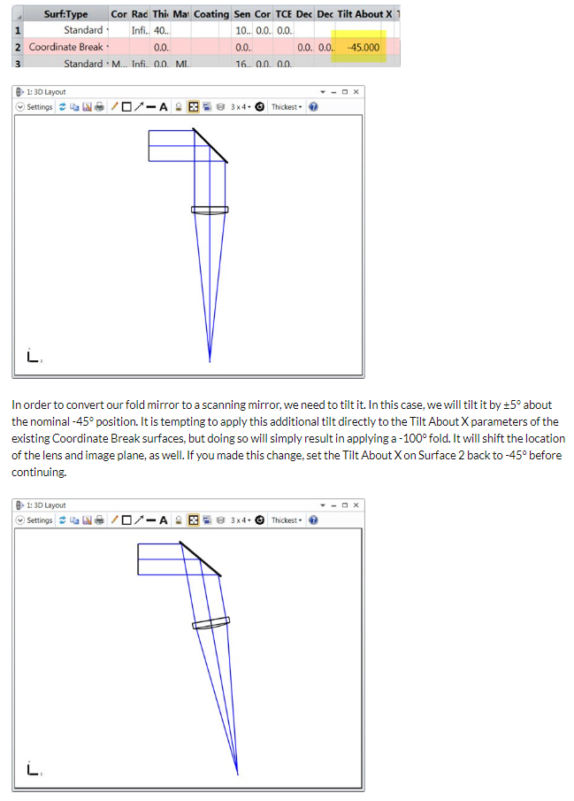
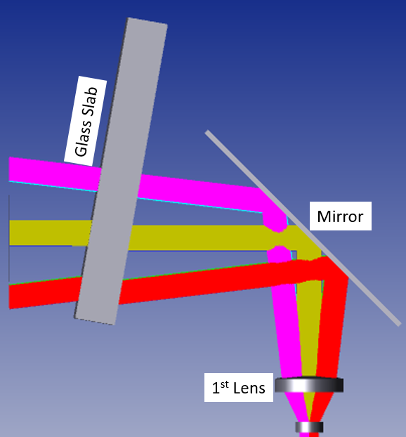
I am trying to analyze the vignetting due to tilt of mirror (from 40 degree to 75 Degree) in the above figure (Mirror is at 45 degree tilt) by retaining the coordinates of 1st lens and Glass Slab. But I couldn’t do that…
- I tried with making 1st surface of 1st lens as global coordinate and try to analyze the effect of mirror tilt, but along with mirror glass slab is also rotating, which is not practical to me.
- I tried with making 1st surface of Glass slab as global coordinate and try to analyze the effect of mirror tilt, but in this case system below the mirror is rotating along with mirror, which is also not practical to me.
So, Is it possible to retain the coordinates of both the element (glass slab and 1st lens) and rotate the mirror alone without affecting the other optical elements in the system?
Thanks.