I am modelling a laser position detection system. I wanted to know if OpticStudio comes with commercially available position detectors like quadrant detectors. If yes, any leads on how to find them in zemax. If no, how does one go about a situation where you have to use a commercially available detector in Zemax.
Hi Micah,
This is not a copmlete answer, but I don’t think you’ll find a readily available quadrant detector in OpticStudio. However, it could be simulated using 4 detectors. I tried my best with a dummy example using 4 Detector Rectangle:
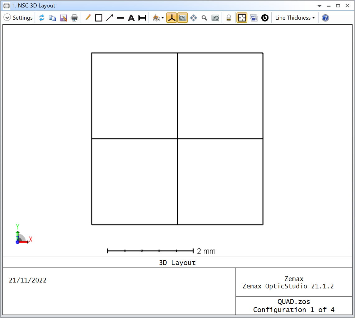
The Detectors are 2 by 2 mm (1 pixel by 1 pixel) and I’m using a Source Gaussian to simulate a 1-mm radius (1/e^2) laser beam. I will attach my file to my reply.
Then, I use the Merit Function and the NSDD operand to know how much power went into the four detectors. I made use of Eq. 1 and 2 from this article:
Developing Laser Spot Position Determination Circuit Modeling and Measurements with a Quad Detector
Except with my nomenclature, the equation is more like:
X = K * ( ( A + D ) - ( B + C ) ) / ( A + B + C + D )
Y = K * ( ( A + B ) - ( C + D ) ) / ( A + B + C + D )
Where A, B, C, and D are the flux reported by NSDD and K is a constant. I wasn’t too sure how to calculate the constant so I did the following:
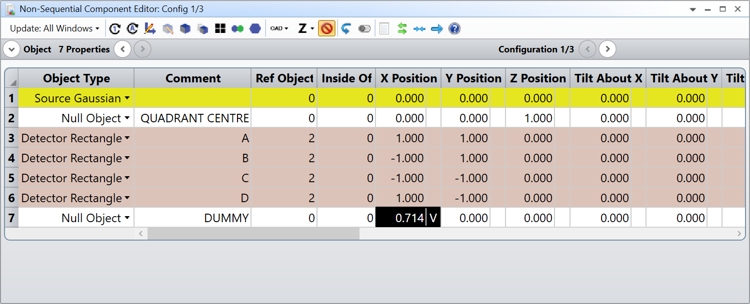
- Add a dummy object, and set its X Position as a variable (it will be our constant K value)
- Add multiple configuration for the X and Y Position of the Source
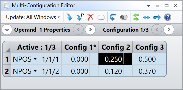
- Target the X Positions of the source in the Merit Function
- Verify the accuracy by reading the Y Positions
I’m sure someone more knowledgeable than me can explain you how to calculate what this constant should be. That being said here are the results:
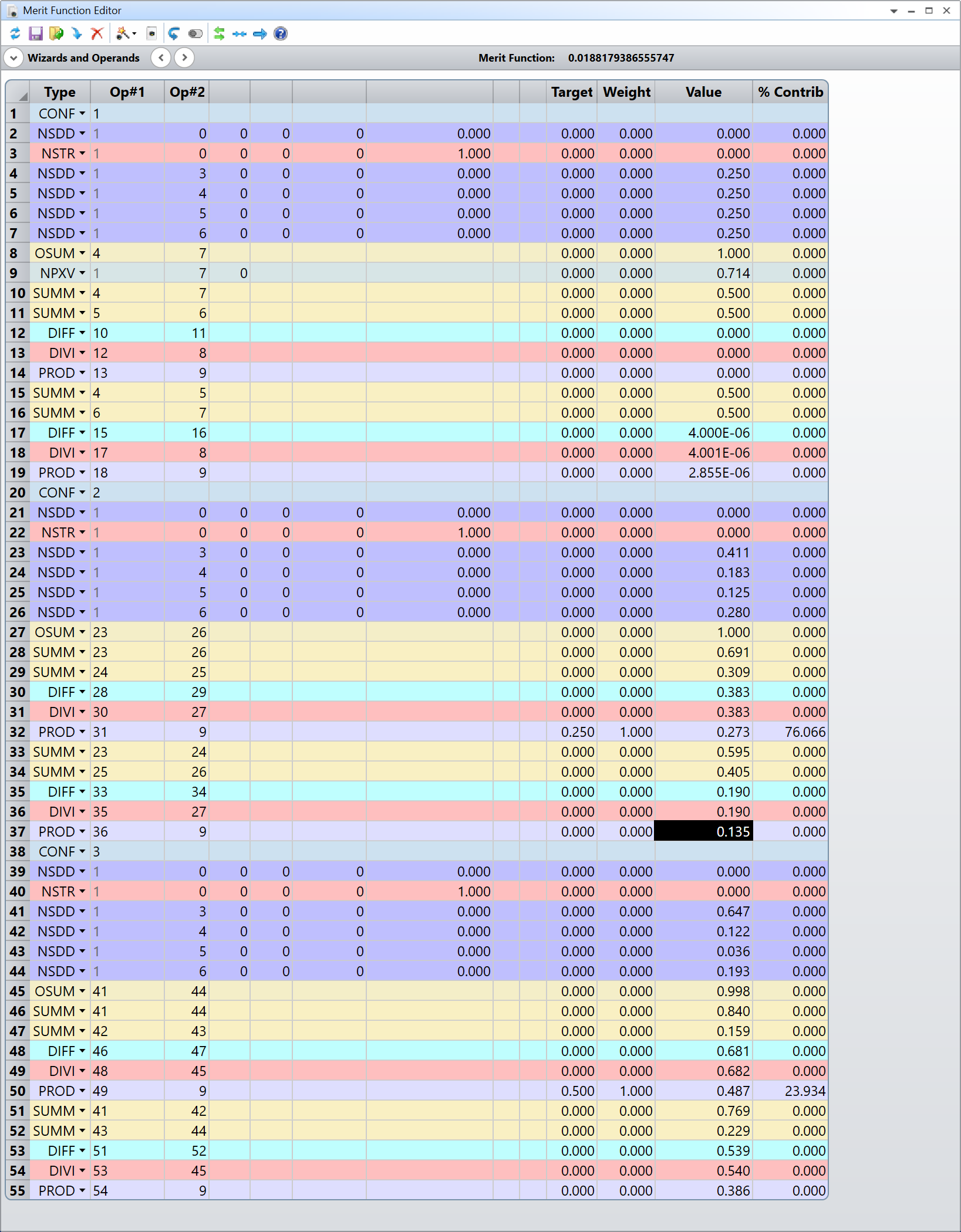
I let you decipher the Merit Function (and ask me about it if you don’t understand it), but the X coordinate is in operands 14, 32, and 50 while the Y coordinate is in operands 19, 37, and 55. For the X positions we have:
X Target | X Reported |
---|---|
0.000 | 0.000 |
0.250 | 0.273 |
0.500 | 0.487 |
For the Y positions we have:
Y Target | Y Reported |
---|---|
0.000 | 2.855E-06 |
0.120 | 0.135 |
0.370 | 0.386 |
The accuracy isn’t perfect, and I’m not quite sure why, but perhaps somebody else can chime in to give more advice.
Hope that helps somehow.
Take care,
David
Hi David
Thank you so much for this tremendous assist. I hope it will help me so much
Hi Micah,
Here is a walk through of my Merit Function. First, notice how the Merit Function is actually split into three nearly identical parts separated by the CONF operands. I basically copy-pasted the Merit Function for the different configurations that describe the beam position. The only operand that isn’t copied everywhere is NPXV. I’m using this to report the value of the dummy object X Position, which serves as our constant K in the formula I gave you (and that we are optimizing along the way).
The CONF operand serves to identify what configuration to use for the subsequent operands. Then, the first NSDD operand (all parameters to zero) serves to clear the detectors. NSTR runs a ray trace. The four consecutive NSDD operands show the total flux of each detector (objects 3 to 6). You then have a first OSUM operand, which sums the total flux of all detectors. This is your ( A + B + C + D ) in my formula above.
Then you have two SUMM operands which are the sum of ( A + D ) and ( B + C ) for the calculation of the X Position. DIFF takes the difference between the two SUMM operands just above, so it is ( A + D ) - ( B + C ). DIVI takes the ratio of the DIFF operand and the OSUM operand, giving you ( A + D ) - ( B + C ) / ( A + B + C + D ). Finally, PROD multiplies the result of DIVI by the constant K (in NPVX). The rest of the operands do the same calculations for the Y Position.
Let me know if that makes sense.
Take care,
David
It is well articulated and makes so much sense. Last one, how did you print the target/ reported values?
Hi Micah,
The target is the actual position of the beam. The beam travels orthogonally to the detector and is centred at the intersection of the four quadrants. The target positions are defined in the multi-configuration editor. In Config 1 the beam (Source Ellipse) is in X Position = 0.0, Y Position = 0.0, in Config 2 the beam is in X Position = 0.250, Y Position = 0.120, and in Config 3 the beam is in X Position = 0.500, Y Position = 0.370.
The reported position are the operands I mentioned in my post originally. Those are the positions calculated with the quadrant photodiode formula. As a reminder: the X coordinate is in operands 14, 32, and 50, and the Y coordinate is in operands 19, 37, and 55. It makes sense that the X coordinate is accurate, because I’m using the target to optimize the constant K. The Y coordinate though is what is calculated from the optimized constant K. I hope that makes sense. Sorry if its a bit confusing, but I don’t really know the maths behind this equation and found this hacky way of deducing K.
Take care,
David
Thank you so much, now it is crystal clear
Reply
Enter your E-mail address. We'll send you an e-mail with instructions to reset your password.