Solved

Point spread function and MTF for factory achromat lens hopelessly low


All, I have an Edmund Optics Achromat for which I am trying to obtain a PSF and MTF for 600, 700 and 800nm. After extensive attempts the PSF and MTF results are hopelessly low to the point where I refuse to believe the results as they do not agree with practical experiments. Any help would be appreciated.

icon

Best answer by Jeff.Wilde 22 March 2022, 02:50

View original

13 replies

Userlevel 7
Badge +2

Hi swhobbs,


I had a quick look at your file, and you might need to give us more detail as to what you are trying to achieve. Without modifying your file, the Merit Function has an error with the DENC operand. This is probably because your system is far from being diffraction limited, and those calculations likely fail. Also, I see three achromats, and not a single one (what I expected). I also noticed some constraints that seem specific to your system in the Merit Funciton that require explanation as well.

When you say your analyses don’t agree with experiments, can you share the data about this disagreement? Do you have a PSF/MTF that you can directly compare with OpticStudio, and if so, can we see it? What is your experimental arragement? Is the STOP located at the correct position?

Take care,


David

Userlevel 7
Badge +3

+1 on what David says.

In addition, in your experiment, what are you using as a source of light? If it is a laser, how big is its 1/e^2 compared to the 19 mm aperture of the lens? You have the system set up with uniform apodization, so it is equally bright across the aperture. Is that what you are using experimentally?

  • Mark
Userlevel 7
Badge +3

To reiterate what Mark and David have said, getting good agreement between experiment and model requires the model to properly mimic your actual setup, being sure to include all of the requisite detail.  My experience is that when doing so, the model will very accurately predict experimental performance.

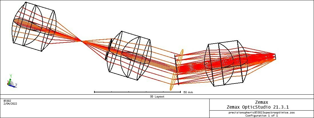
In your model, which I’ve simplified by (1) removing the rectangular slit aperture, (2) reducing the entrance pupil diameter to 15.0 mm, and (3) re-focusing, we see the aberration is indeed quite large (it’s predominantly a combination of spherical and axial color).  Here is a snapshot of the layout, spot diagram, and the axial focal shift.


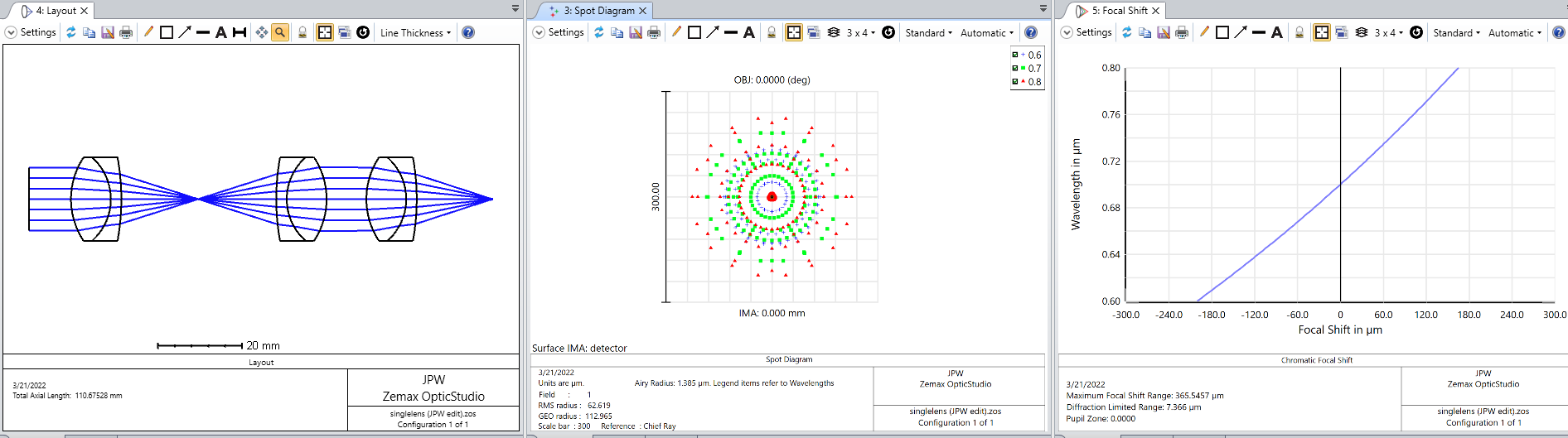
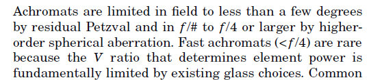
However, this is an f/1.6 system (your original model is f/1.38) with a uniformly collimated input beam having equal weighting across wavelengths from 600-800 nm.  Typically achromatic doublets, and particularly off-the-shelf doublets, perform best for f/4 or slower systems.  Here is what Bentley and Olson say in their SPIE Field Guide to Lens Design (p. 30):


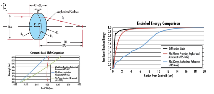
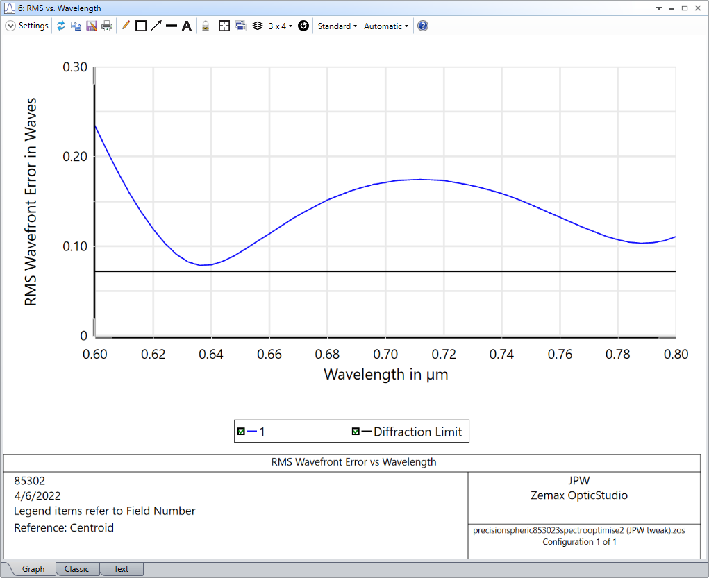
It sounds like your experimental setup may be working to your satisfaction (perhaps your input is a small-diameter collimated Gaussian beam with less than a 200-nm bandwidth?), but if not, and you need to reduce the aberrations, then you may want to consider using a precision aspherized achromat (see: Precision Aspherized Achromatic Lenses).  For example, here is an f = 25 mm lens from Edmund Optics (85-302):


You can see it’s performance is dramatically better than a conventional doublet with spherical surfaces.  If I use this lens in place of the one in your model, then the performance is much better.  In fact, at 700 nm, it is essentially diffraction-limited.


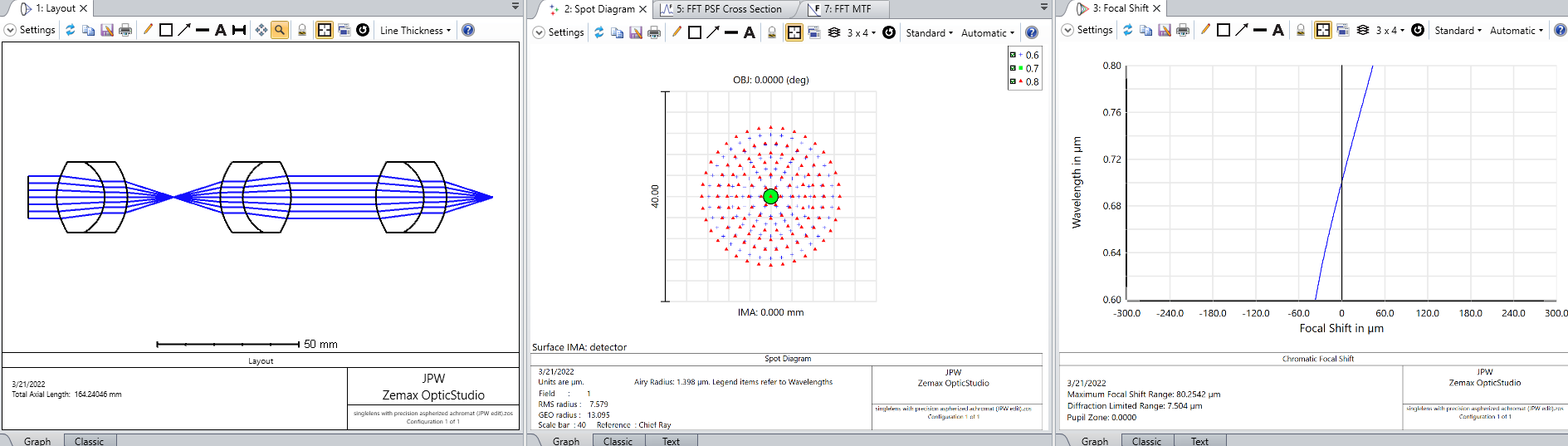
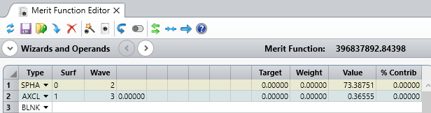
Here is a comparison of the aberrations for the two systems:

Edmund 49-956 (standard doublet), f/1.6


Edmund 85-302 (precision aspherized doublet), f/1.6


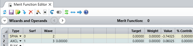
You can see the precision aspherized doublet yields a 20X reduction in spherical aberration and a 4.6X reduction in axial chromatic focal shift.  Of course the aspherized doublet is more expensive, but you get what you pay for.  Hope this helps...


Userlevel 7
Badge +2

This is excellent @Jeff.Wilde, thanks for sharing such thoughtfull and detailed information.

Thank you so much for your responses, they are very thoughtful and I have gained much understanding based on them. I am actually starting to believe what this program is giving me. I have tried recreating a dispersive spectrometer based on the aspherized doublet and am finding improved performance than the standard achromat. However I find that I am still getting quite a lot of distortion in the 600 and 800nm areas (wavelengths are 600, 700 and 800nm, aperture of 18mm). I have tried adding a negative lens near the detector to try to flatten out the field curvature however the aberration was worse. I am not sure what else to do here to make it better.


Userlevel 7
Badge +3

@swhobbs  It would be more helpful if you could attach a zar version of your model.  For construction of a spectrometer, off-axis aberrations have to be taken into account.  I think most designs are based on curved reflective gratings.  For example, see:  Flat-field concave gratings simulation

Apologies, please find attached the Zar file - I had trouble uploading to the forum. I shall also have a look at the link you sent. Thank you again.

Userlevel 7
Badge +3

@swhobbs  According to your revised layout, the aberration really isn’t that bad, especially for an NIR spectrometer constructed using off-the-shelf lenses.  After adjusting the focus by -0.093 mm (to better distribute the aberrations across the defined spectrum), here’s the RMS wavefront error vs wavelength:


The average aberration is about 2X greater than the diffraction limit.  If you absolutely need diffraction-limited performance, then you may need to pursue a more complex custom design.


Thank you so much for your help and support. I have learned a lot from the helpful guidance on this forum. I am trying to customise the design by using two off axis parabolic mirrors (an objective, a collimator, and finally a focus lens). Slit and diffraction grating will follow; however I am unable to get 2 X parabolic mirrors to behave properly. I need to get incident light to reflect from the first mirror to the second, and then pass to focus through the lens. As can be seen something is very wrong. I have followed the two parabolic mirror tutorials on Zemax however find the trouble starts by trying to have two parabolic mirrors. Any help would be great - and sorry for the continued requests for help.

Userlevel 7
Badge +3

@swhobbs   Yes, I see your layout is quite a jumble.  To be honest, I don’t quite understand what sort of overall layout you are trying to achieve.  It would be helpful if you can provide a sketch.

Please find a rough sketch of what I am trying to achieve. I have deliberately left out the grating and slit in the Zemax file as I need to get the rest of the optics to align first. Thank you again.

Optical rough sketch


Userlevel 7
Badge +3

@swhobbs   I’ve reviewed your layout sketch and can provide some guidance, but first I think it would be better if you re-post this latest question in a new thread that includes off-axis parabolic (OAP) reflector in the title since the topic has now deviated quite a bit from your original question.

Thank you for your feedback.

I have created a new topic here if this is of help:


Reply