Solved

Flat field concave gratings simulation

  • 11 February 2022
  • 12 replies
  • 1274 views

Hello,

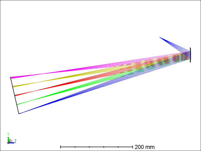
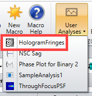
I am currently trying to use a flat-field concave-gratings in an optical spectrometer setup.
The latter has improved shape and design so that the grooves are neither parallel nor equidistant. The main purpose is to minimize astigmatism and coma.

(typically: https://www.ssioptics.com/product-category/diffraction-gratings/flat-field-concave-gratings/)

I am wondering which procedure I should follow in Zemax to create this type of Grating shape and/or if anybody else worked using this king of gratings using Zemax?

I am working in sequential mode since it is the one which I am feeling the most confortable with. I used the surface type diffractive grating to create my gratings combined with a concave curvature. However I am quite sure it is not the best way to simulate it, and I will certainly not have a proper estimation of my astigmatism and coma.

I am open to invest time to learn non-sequential mode if it is needed.

Thanks a lot in advance for your help and suggestions!


icon

Best answer by Jeff.Wilde 24 February 2022, 19:57

View original

12 replies

Userlevel 4
Badge +3

@Michael Cheng  - I looked at the link provided by @Julien.Gateau  and it appears to me that modeling that part would require a 2D (rotationally symmetric even?) RCWA grating DLL. Do we currently have such a thing? Or do we have any option to model a diffraction grating with a user defined spacing?

Userlevel 7
Badge +3

I’ve not heard of this type of grating before but looking at the website posted I think that the Optically Fabricated Hologram would handle this. The great power of the OFH is that the grating is formed by the interference between two other optical systems, and so the fringes do not need to be parallel or equidistant.

Userlevel 4
Badge +3

Good tip, @Mark.Nicholson !

For @Julien.Gateau  here is an article on OFH: https://support.zemax.com/hc/en-us/articles/1500005489901-How-to-use-the-Optically-Fabricated-Hologram-to-correct-for-aberrations

Userlevel 6
Badge +2


I agree with Mark. This is probably manufactured by two beam interference. The webpage also mentioned this is a holographic blaze grating.

I think you could start from a simple hologram and then change to a more complicated OFH. I have attached an example for your reference.

Userlevel 7
Badge +3

The simple holograms are all some variant of a point source and so will produce straight line fringes. The described hologram has varying line spacing and orientation, and so will need the OFH.

The next question is: does the vendor provide the information for you to construct the two fabrication systems?

Userlevel 7
Badge +3

The design of a flat-field holographic grating spectrometer has been discussed in detail in the literature.  A couple of references include:

  1. Lerner, et al, “Aberration corrected holographically recorded diffraction gratings,” Proc. SPIE 240, 1980.
  2. Huang, et al, “Design of aberration-corrected flat-field holographic concave grating by parameter optimization,” Optik 123, 2012.

Interference of two point sources on a concave surface can be used to construct the required grating.  In general, two mutually coherent point sources will produce an intensity interference pattern described by a set of hyperboloids (e.g., see Goodman, Intro to Fourier Optics) :

The general architecture for a flat-field holographic grating spectrometer, based on point-source interference recording, is shown below (ref: Lerner, et al, “Flat Field Imaging Spectroscopy Using Aberration Corrected Holographic Gratings,” Proc. SPIE 263, 1981):


Here’s an example of such a configuration, designed to operate from 0.19 um to 1.0 um, based on the Hologram 1 surface in OpticStudio:


In this case, the locations of the recording point sources are determined by optimization via a merit function that places the diffracted center wavelength at the midpoint of the linear detector array as well as by minimizing the rms spot size at the center and the two ends of the spectrum (on the pre-defined detector surface).

Regards,

Jeff
 

Userlevel 7
Badge +3

Oh, great stuff. Thank you Jeff.

Thanks a lot to all for your answers!
 

@Jeff.Wilde Thank you for your references and Zemax simulation overview. I am currently having a look at the Hologram 1 Surface and  reproducing what you did.

Sorry for my lack of knowledge, but which merit function is used to optimize the position of the diffracted centre wavelength at the midpoint of the linear detector?


@Alissa Wilczynski  @Michael Cheng@Mark.Nicholson  I will have a look to the Optically Fabricated Hologram, the article sounds also interesting.


Concerning the information they shared, they only gave to me a pdf giving distances and angles vs wavelength (see attached document).

From the latter, I can certainly verify if the Zemax simulation and the coordinates they have are fitting to each other.

Maybe I can also use these values to add some constraints in the optimization loop?


Userlevel 7
Badge +3

To center the diffracted spectrum on the linear detector array, you can use the REAY operand to direct the chief ray for the center wavelength to the y=0 coordinate position on the detector (which in my model is the center of the detector in its local coordinate system).  

Userlevel 7
Badge +3

Also, make sure you select ‘ignore lateral color’ in the optimization wizard. For a spectrometer, lateral color is the intended behavior, and not an aberration.

I wouldn’t worry about he Optically Fabricated Hologram if the simpler hologram surfaces do what you need. 

Userlevel 7
Badge +3

Yes, it’s definitely important to have the MF wizard ignore lateral color. 

One more quick note.  It’s easy to see the spatial frequency chirp across the hologram by using the “Hologram Fringes” utility which is included as one of the ZOS-API User Analyses programs:


For the demo model shown above, we can see the hologram fringe frequency varies from 262 to 284 cycles/mm.

For more details, see: Analyzing hologram construction fringes with a ZOS-API User Analysis

I managed to repeat your simulation and almost obtained similar results. I am now working on the implementation in our optical setup.

The operand REAY is indeed quite useful! Good to know

Having a series of angles vs wavelength from their file, I also used the operand RAEN, which also seems to help configure the flat field grating.

Quite an interesting approach. I would like to thank you all again for your help in this optical design process.

Reply