Hi,
By this question I am trying to understand how Zemax and in general how raytracing and geometrical optics work.
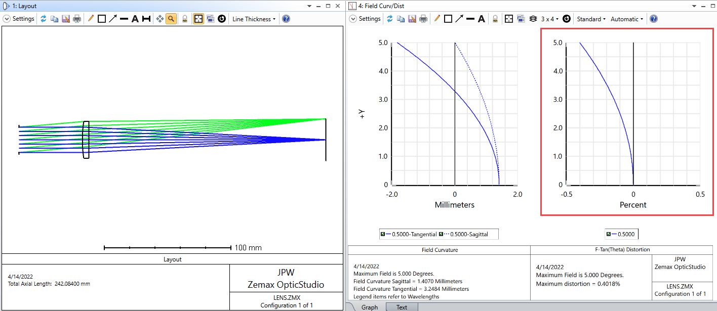
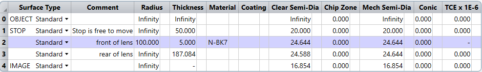
As part of my learning ZOS-API, I am trying to raytrace as a function of hy (normalized field coordinates along y-axis) at px = py =0 for a lens with the specs below
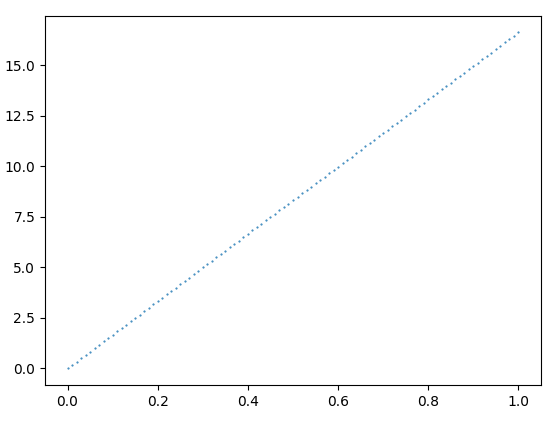
OpticStudio can plot the ray coordinates as function of entrance aperture but here I am trying to plot the ray coordinates as function of field coordinates). When the px = py =0, so the aperture dependent terms will be zero and only the Distortion terms (nonlinear field-dependent terms) are present. However, raytracing with Zemax (I use ZOS-API) results a plot like this (x-axis is the 0 < hy < 1 and y-axis is the ray coordinates.
My Question
Why this plot is linear and non-linear terms are absent? I found that by changing the px and py values this plot does not change a lot.
Here is the important parts of my Python code based on ZOS-API. After the lens and aperture are created a QuickFocus is run to put the image plane at the lens focus.
max_rays = 100
px = 0.0
py = 0.0
hx = 0.0
hy = np.linspace(0,1,max_rays)
for i in range(0 , max_rays):
    RayTraceData.AddRay(1, hx, hy[i], px, py, Enum.Parse(ZOSAPI.Tools.RayTrace.OPDMode, "None"))

raytrace.RunAndWaitForCompletion()

RayTraceData.StartReadingResults()