Hi everyone.


I would like to be able to specify a number of sources and their positions, and use the optimization function to help me find the best power settings and positions for the flux at a given detector to between a given maximum and minimum.


There could be many sources, and at the moment all I can do is use an imported CAD file, explode it, and create a source based on one of the elements.


What I have been able to do from that is to create an array of sources, so that the NSE grid doesn't get too overcomplicated, but how can I then use the optimization function to move them independently?  For instance, if in a 2 by 2 array, can the optimization function move just one element to a different position?


If this is not possible, do I have to create a single object in the NSE for each source?  For my purposes, that seems rather unwieldy, because at the moment I have to specify the CAD arrangement as the parent object, and I presume I will have to have a new CAD import for each source.


Given that we could have hundreds of sources, I am looking for a more streamlined way of doing this.


Thanks in advance.

Hello Adrian


Source arrays are defined by these parameters:


You will be able to modify these properties in the optimization but you won't be able to move one source individually. So I am afraid you would have to create separate sources if you want them to move separately. 


From your message, it seems like this is not a good option so I'd like to get a better idea of what you are doing. What kind of source are you using? Is it the Source Object ? With Source Objects, you can  have multiple sources using the same parent object.


Another option would be to keep working with an array and then if a source needs to be switched off, you could for example add an absorbing detector polar around. Then you could add a new source that can be moved.


I have also looked at the array object but unfortunately you can't create a source object or a source imported from an array object.


I don't have a great workaround but if you can share more details that may help.


I have attached a simplified file to discuss.


Feel free to open a case if you do not want to share details with the whole community.


Thank you.


Sandrine


Hi Sandrine.  Jo here, in place of Adrian now.


Thank you for your answer.


What I am trying to do is to place a set of lamps onto a ceiling, and to be able to move them around to ensure an even level of radiance at the detector.


The source objects can be created individually, but really they have to each be placed (and move) along with the whole lamp assembly, as part of the lamp contains the parabolic reflector faces, which I have set as of type 'MIRROR' so that the rays are reflected outwards from the lamp, so it is not possible to create a set of sources that refer back to one parent item.


Best Regards


Jo


Hi Jo,


Thanks for your post!


In this case, if you would like to move the sources individually, and not in a regular array, and you also need to model the case of the lamps, I think the best workaround would be to use an individual source object for the lamp itself, using the same parent object for every lamp, and to use a Boolean CAD object to model the case for each lamp individually again. For the Boolean CAD objects, you may use the same imported and exploded assembly for every lamp and position them relative to the individual source objects. The local coordinate system of the resulting Boolean CAD object will be the same as the local coordinate system of the first object listed in the boolean Control String, while the global object position and orientation is set by the object position and tilt parameters in the same manner as all NSC objects. In this way, you can model every lamp with only 2 objects, one source and one boolean, and you only need to do the import and explode the CAD assembly once for the whole system.


You may find more information about the Boolean CAD object type in the Help file at:


The Setup Tab > Editors Group (Setup Tab) > Non-sequential Component Editor > Non-sequential Geometry Objects > Boolean CAD


and in these knowledgebase articles:


How to use the Boolean CAD, Boolean Native and Compound Lens objects, and the Combine Objects tool · MyZemax


Improving non-sequential ray tracing speeds with nested and Boolean objects · MyZemax


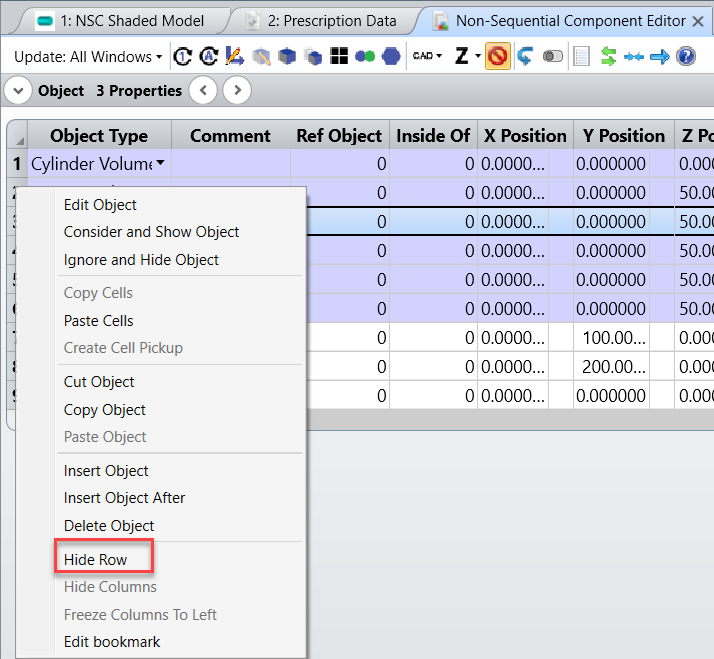
Additionally, you can hide the some lines in the NSCE editor to make it more readable:


I hope this helps, but if you have further questions, please let us know and we will be happy to help!


Best,


Csilla


Hi Csilla.


Thank you for that.  Unfortunately, I can't even combine two of the exploded CAD objects, because I get the error message: 'Cannot create object 17 because there are too many faces in the source objects.'


In any case, I have found a solution that works for me: I have created the source tubes and placed them where I want, then I have used the 'Pickup' function to place the exploded CAD components relative to each source tube.  As a result, I have the table shown belos, and I can group the sources at the top so I can see them all.


As an extra question, can you tell me why one of the lines is in dark grey?  Its colour coding is set to 'default', as are all the others.


Is there a link that tells me what the colour coding is?


Thank you.


Best Regards


Jo


Hi


The table didn't show in the previous post, so here it is here.


Best Regards


Jo


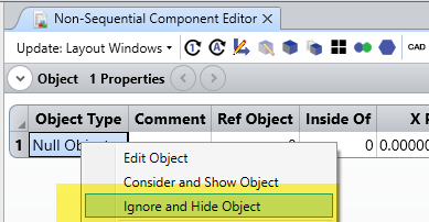
A row is dark grey when the object is ignored by rays (under the Object Properties...Type...Rays Ignore Object...Always).


This can be set up quickly by right clicking on the row:


Well I don't know if this is defined in the help file. I didn't find it, but maybe I looked too quickly:


- Yellow is for a source


- Dark grey is when rays are ignoring an object


- Light grey is when the material is set to MIRROR


- Purple is when there is a material


Reply