Question

OPD: Reference sphere and exit pupil

  • 12 September 2023
  • 8 replies
  • 464 views

Userlevel 1

Hello Optic Studio friends,

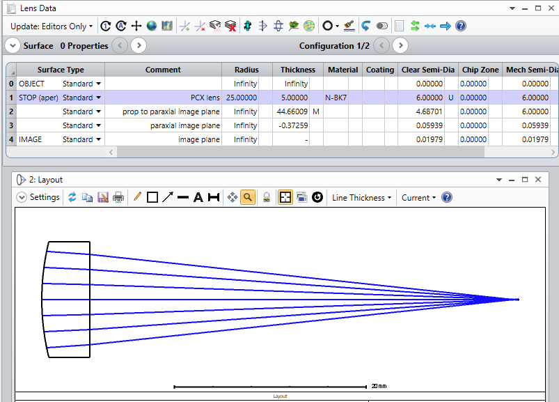
I have a question about the OPD calculation for an on-axis finite-finite imaging system.

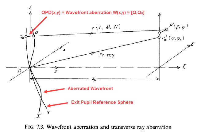
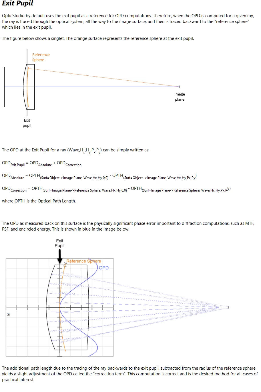
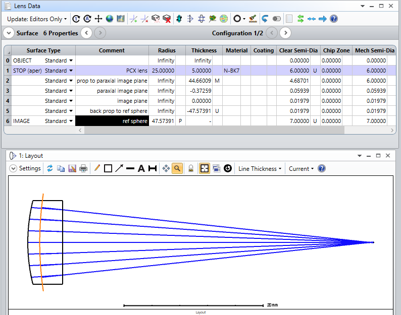
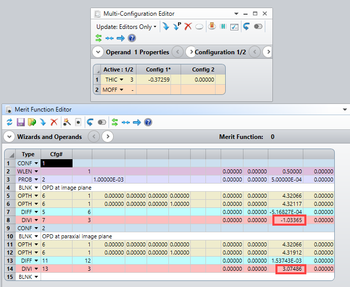
I have understand that OS calculates the OPD based on the reference sphere and that the OPD is calculated in the plane of the exit pupil.

How does Zemax calculate the exit pupil? Does it consider pupil aberration? Or does it assume that the pupil is just a plane? And is the pupil position the position you get when using paraxial ray trace equations (...what means that aberrations of the system are not considered)?

And I have another question regarding the reference sphere. Where is the center of the reference sphere located?
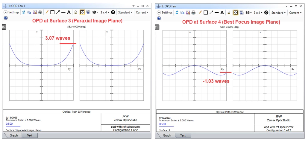
Is it located in the paraxial image plane? 

Thanks and kind regards
Dirk


8 replies

Userlevel 7
Badge +3

Note: This entry has been edited after its first posting in order to correct a few errors (see further details below).

Hi Dirk,

The exit pupil plane is the plane where the paraxial image of the stop is formed when viewed from image space.  The OPD for an arbitrary point on the image plane (i.e., the point where an arbitrary ray from a given field point intercepts the image plane, typically the last surface in a sequential model) is defined relative to a reference sphere centered on a reference point in the image plane.  OpticStudio uses the chief ray intercept for the reference point.  The reference sphere goes through the center of the exit pupil plane. 

Here is a figure from Welford (Aberrations of Optical Systems) that illustrates the OPD:

The OPD is defined as [Q,Q0].


Below is an excerpt from the help documentation that describes how OpticStudio computes the OPD.  It may not be immediately clear that the calculation below corresponds to the OPD as shown above, but with some thought you will find that they are indeed the same.


Regards,

Jeff

Userlevel 1

Hi Jeff,

thanks for your answer.

You wrote “The OPD is defined as the optical path difference between (a) the OPL from the reference point to the reference sphere, and (b) the OPL from the image point to the reference sphere.”

For me, that does not make sense because this definition does not consider the aberrated wavefront.
Please doublecheck...

First question:

From my understanding in the figure you posted, P0’ is the reference point (=center of reference sphere). Right?
The left vertical axis is the plane of the exit pupil. Usually the pupil is located where the chief rays intercepts the optical axis. Does OS consider, that chief rays of different field points do not have the same interception point with the optical axis (aberrated exit pupil)?

Second question:

What is P’ in the figure above?

Third question:

Do we have the same understanding that OPD is [Q Q0]=[P’ Q0]-[P’ Q]? I yes your definition would be wrong. 

Best regards 
Dirk


Userlevel 1

Hello,

as far as I understand the wavefront map in OS is just another illustration of the OPD fan. 
I allways thought that the wavefront map shows you the aberration of the wavefront. But this might be misleading:

I have a perfect finite-finite on-axis system which consists just of a paraxial lens, but the last surface in my seq. model is not perfectly located where the (paraxial) image is (...because of some defocus), then the wavefront map and the OPD fan both show significant wavefront aberration, although the wavefront in image space is perfect spherical…and thus unaberrated.

Is there the possibility to plot the OPD fan or the wavefront map in OS without the defocus term?

Kind regards
Dirk

Userlevel 7
Badge +2

Hi @Dirk.Broemme,


Regarding your last question. This was partially adressed here:

And as is described in the knowledgebase article: https://support.zemax.com/hc/en-us/articles/1500005487721-Why-is-the-optical-performance-sometimes-different-at-the-Image-surface-versus-a-co-located-surface- that the post reference, you could have a dummy surface at the location of the paraxial focus to remove the defocus from the OPD fan and the wavefront map, with some limitations described in the Help file and in the article.

Another way would be to extract the OPD fan or wavefront map with the ZOS-API and remove the defocus yourself, if that makes sense.

Take care,


David

Userlevel 7
Badge +3

Hi Dirk,

Yes, my first posting was only partially correct.  I edited it and will provide more detail here.

The OPD = [Q,Q0] = [P,Q] - [P,Q0] where P is the object field point.  But, the ref sphere and the aberrated wavefront coincide at the origin of the exit pupil, so we have:

OPD = [P,0] - [P,Q0].

To calculate this in OpticStudio, we can trace a ray from an object-space field point to the image plane, and then back propagate to the reference sphere, and calculate the OPL for this case.  Then we can do the same for the chief ray and take their difference.  So,

OPD = [P,P0’,0] - [P,P’,Q0] = ([P,P0’] + [P0’,0]) - ([P,P’] + [P’,Q0]).

Here P’ is the point where the ray of interest intercepts the image plane, and P0’ is the chief ray intercept with the image plane.  Note that the back-propagated OPLs, namely [P0’,0] and [P’,Q0], are negative quantities.

Here is an example with a simple plano-convex lens:

here are the OPD plots at paraxial focus and best focus (where defocus has partially compensated spherical aberration):


We can easily modify the optical path to include the reference sphere and then calculate the OPD values in the merit function using one configuration for best focus and a second config for paraxial focus.


We find OPD values (in waves) that agree with the marginal ray values in the OPD fans above.

In the case of pupil aberration, I assume that for off-axis fields, OpticStudio continues to use the actual chief ray in the calculation even if it doesn’t go through the exact center of the exit pupil plane.

Regards,

Jeff

Userlevel 1

@David Nguyen 

Hi David,

thanks for your answer. This helps! In terms of the wavefront map in OS I would like to see not only a tilt removal button, but also a defocus removal button;-)


One more question regarding the Seidel aberration coefficients in OS also describing wavefront aberrations:


Why does OS calculate the wavefrontaberration in the OPD fan plot in a way so that the result is dependent
on the position of the last surface in the seq. Zemax model and why does OS calculate the Seidel coefficients not dependent on the position of the last surface in the seq. Zemax model?

As far as I know, both - the OPD and the Seidel coefficients - are calculated on the basis of a reference sphere.
 

Kind regards

Dirk
 

Userlevel 7
Badge +3

Seidel coefficients are computed surface by surface using only paraxial rays. OPD is cumulative for the whole system using real rays, with a chief-ray centre reference sphere subtracted.

The difference between OPD at the IMAge surface and any other surface is that we use a marginal ray height solve to set the ‘virtual’ image location on any other surface to eliminate focus, otherwise focus would simply dominate on every surface. When measured on the IMAge surface we get the OPD as seen by that surface looking into the pupil.

Note as you go off-axis, the reference sphere is tilted to remove, erm, tilt. We call this a centroid reference by analogy with the spot size, so it is not strictly a chief-ray reference anymore. However, the centroid reference is the physically significant part that affects image quality.

  • Mark


Userlevel 1

@Jeff.Wilde 

Thanks Jeff! Now we have same understanding:-)

Best regards
Dirk

Reply