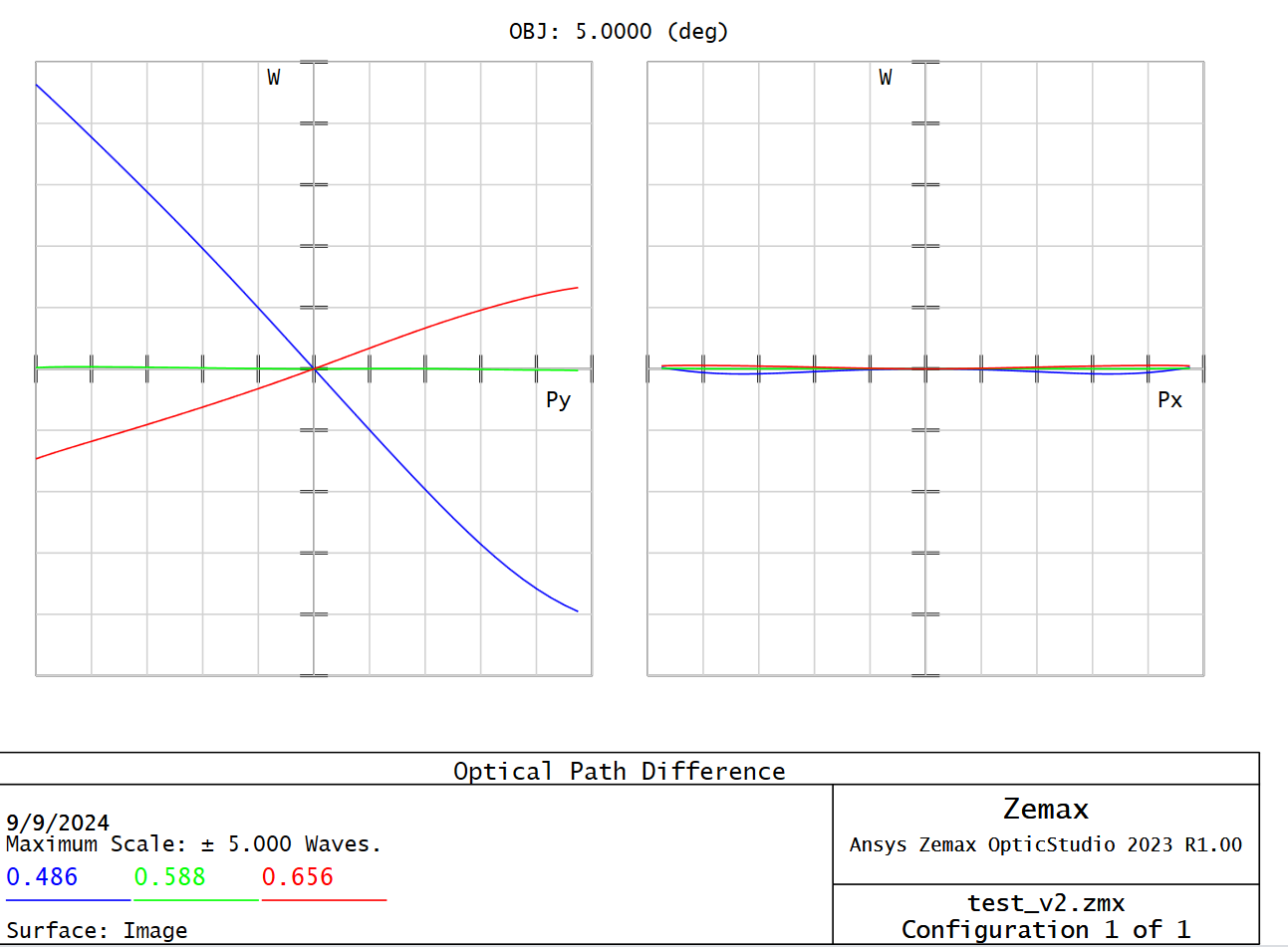
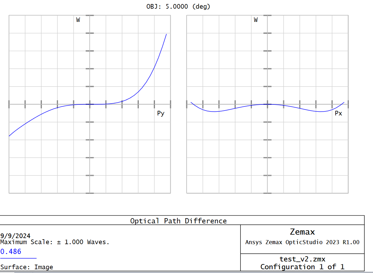
When I select OPD Fan for a 5 degree field, I get this:
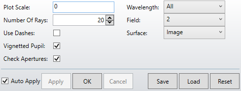
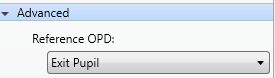
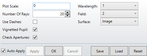
These are the settings used.
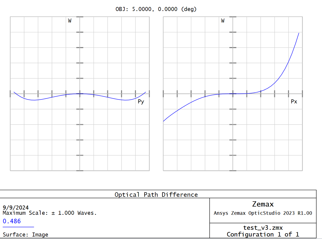
However, when I now select just 1 wavelength (same field, same system), I get something completely different in my “OPD Fan” values:
The system is the exact same in both cases, and I confirm that the values change in the text version when selecting a single wavelength.
Does this have to do with “lateral color” and how it is displayed in the OPD Fan plot (I expect my system to have lateral color for reference)? Or is it something else?
Lateral Color (plot + in system diagram) for reference:
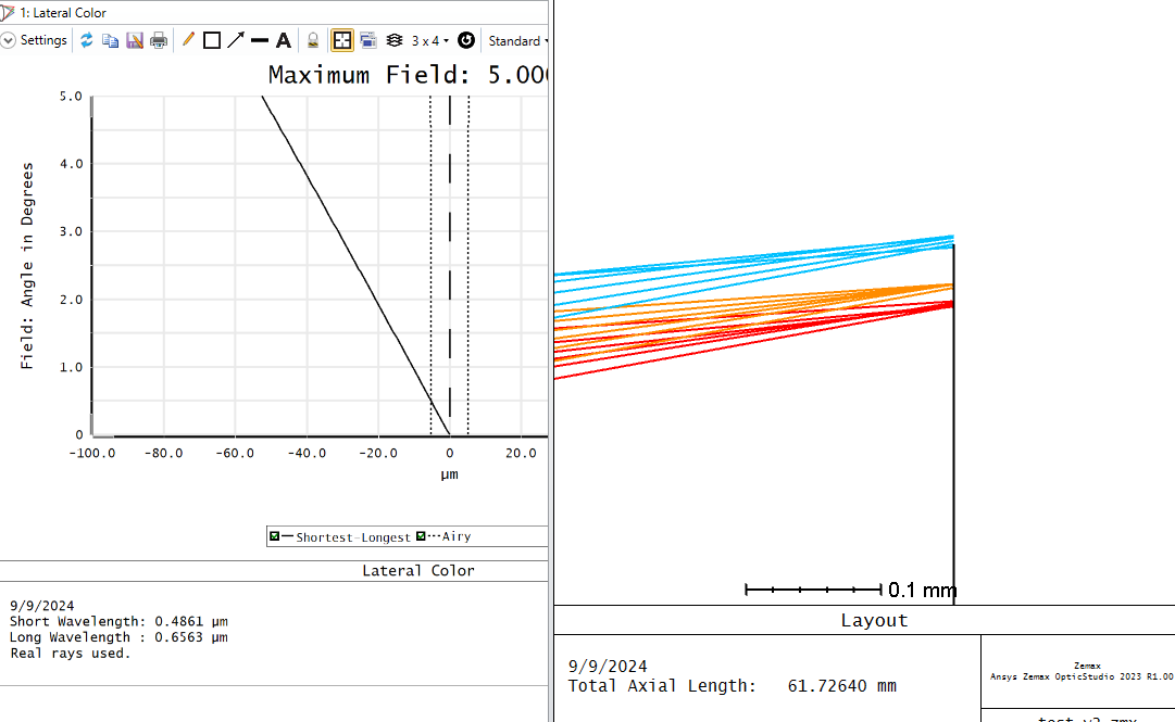
System Information: I am modelling a GRIN (Gradient Refractive Index) lens design using a custom *.dll (nothing too fancy, just adds in wavelength dependence based on custom materials) extensions. This is a singlet that I was testing for off-axis light.
Edit:
Same effect happens if I switch x/y fields around:
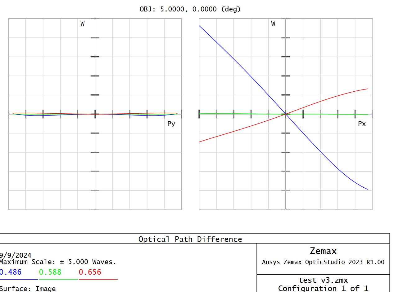
Where OPD when selecting one wavelength doesn’t match the other.