Solved

Off-axis mirror - new surface type

  • 26 September 2021
  • 5 replies
  • 1136 views

Userlevel 1
Badge

Hi Everyone,

I try to implement off-axis prabolic mirror (Diameter 300 mm, focal length 1500 mm and off-axis angle ~10 deg [off-axis distance 262 mm]). In the classic way it is quite easy and well described

https://support.zemax.com/hc/en-us/articles/1500005486541-How-to-model-an-off-axis-parabolic-mirror

but when I try use new feature in OS realease 21.3 I can’t achive good results at first time.

Sandrine Auriol from Zemax team help me with my problem. So together we decide to create new topic. We think it will be helpful for other users.

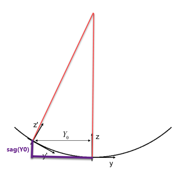
If we have a look at this sketch from the help file, the Off-axis Conic Freeform is defined in the new (x’,z’) coordinates:

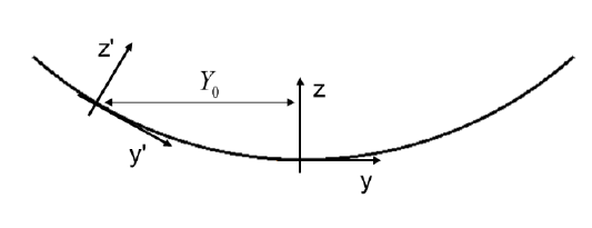
So we need to add the tilt -9.98 degrees. In the Off-Axis Conic Freeform, it is half this value.

We add this angle as a fold mirror.


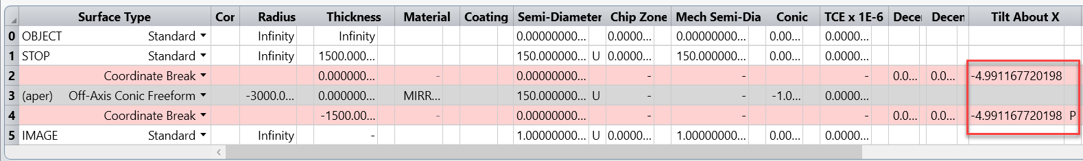
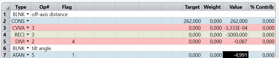
This tilt is actually easy to calculate.

The angle is = atan(sag(Yo)/Yo)

Sag(Yo) = curvature * Y0^2 (no bottom term as it is a parabolic with a conic constant of -1)

So angle = atan(curvature * Y0^2/Yo) = atan(Yo/Radius)


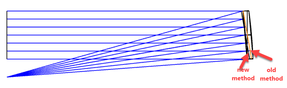
What’s more. I noticed that distance from OPA to image plane is different in both solutions 1523,06 mm vs. 1511,44 mm.

OLD NEW
1523,06 mm 1511,44 mm.


In the attachment you can find new and old OPA implementation.


What do you think?


Best regards,

Maciej


icon

Best answer by Sandrine Auriol 27 September 2021, 12:39

View original

5 replies

Userlevel 4
Badge +2

That's great, thanks for sharing Maciej!

Userlevel 6
Badge +2

Hello Maciej

Thank you for posting this.

The distance from the OPA to the image plane seems different but it is not. It is just that we calculate it from a different plane.

  • In the “old” method, we are at the parent of the off-axis parabola in Z (then we decenter in Y and tilt).
  • In the “new” method, we are at the origin of the off-axis parabola.

So basically the difference between both methods is roughly the sag of the parabola at Y = Offset.


To demonstrate, I have merged your two files in one and here is what you can see when you display both configurations on the 3D layout:

I have attached my file.

You can check the prescription data:


I hope it helps.

Sandrine

Userlevel 1
Badge

Hi Sandrine,

Many thanks for your post and for helping me understand all the details. Now everything is clear.

Best regards,

Maciej

Hello Team,

I noticed in the provided OAP file that the norm radius in the new method has been set to 150. I'd like to understand the rationale behind choosing this specific value, especially when considering only the conic constant -1 (without polynomial terms). Could you please provide insights into the selection process for the norm radius in this context?

Userlevel 3
Badge

Normalization radius (Norm Radius), All ray-intercept points are divided by this number to determine the x and y coordinates for polynomial evaluation. (From Zemax Manual)

Since 300.0 mm is the mirror diameter, 150.0 mm is chosen as norm radius. But it is immaterial at present as there are no polynomial term are used in design!

Norm radius is a number to which the polynomial coefficient will be normalized, Zemax default value is 100 for norm radius, but is it recommended to keep norm radius slightly greater or equal to surface radius at which it is used.

Even if optimization is done for 100 mm (default Zemax value) norm radius, at final stage of the design it can be brought to desired norm radius as per surface diameter by only optimizing the polynomial coefficients. There will not be any performance degradation by doing so.

Reply