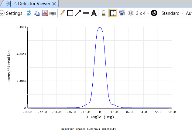
I am working on a design that involves an array of sources.  To speed-up simulations, emitter/source details are reduced to saved ray-set files.


FILE-A:   (Emitter Ray-Set)

I generate a source file (ray-set) by combining an LED source with a custom TIR lens and a detector.  The detector is placed following the output face of the TIR lens.  The captured rays are then saved to a  (*.SDF) file. 


FILE-B:.. (System)

I create a larger system model, that involves an array of “n” emitters.  I setup “n” sources, using the saved  (*.SDF) file above.  I place a detector between the sources and downstream optics.   Those rays then propagate forward. 


The issue I am having is that when I check the angle of the rays from File-A] incident upon the detector following the TIR lens , it is significantly different than the angle of the rays I get from using the “generated sources” tFile-B]


I measure around 18 degrees (half-angle) in dFile-A] with the TIR lens, that I am using to generate the source file (ray-sets).  But I only measure about 13 degrees when using that generated source file (ray-sets) in tFile-B]  Any ideas why that might be the case? 


The TIR lens, of cFile-A] that generates the source file (ray-sets) is a boolean object. 

Could that be messing something up?   Any help would be appreciated.  Thank you. 

The thing that springs to mind is that when you trace your .SDF rays, make sure they start in the same refractive index medium as they were saved in.


Mark’s advice is good. Similarly, I would also add that if you are working with an object like a Boolean near your sources, you want to make sure that the Inside Of parameter is set to that object if the rays are starting inside any of the parent objects in that Boolean, even if the parent object is removed. So if you had a Boolean defined by A-B and the sources you are creating start inside the region that would be object B, make sure Inside Of is set to that Boolean object.


-----»        This SOLUTION worked  BEST  !!    ------------

FROM:   KEVIN SCALES:  (Response #2)

It looks like the differences you are seeing are an artifact of the detector resolution. When I changed the pixel resolution to be 101 by 101 for each example, the graphs looked very similar, with a reduction in intensity for one because of passage through some materials.
 
Direct:
 
?name=image.png
 
With system:
 
?name=image.png
 
I recommend using higher pixel counts and I like to use an odd number so there is always a center pixel where the intensities are at their peak (in a non-tilted system). I think those two changes clarifies what's happening here.
 

Best regards,
Kevin Scales
Application Engineer II

Zemax, LLC.


Reply