Could you please help me about how I can design 3 nanostack laser diode in sequential mode. I added the laser diode that I want to design.

Hi Ceren,


Modeling the laser diode in Sequential Mode will be slightly limited. I can think of a couple options that would get you close.


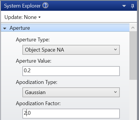
The first would be to set the aperture to Object Space NA to get the proper divergence. If there are different divergences in the X and Y axis, you can put a ParaxialXY surface directly after your object plane. You also may want to set the apodization to be Gaussian, to represent more rays propagating near the center of the Object Plane. 


If you need more of a customized apodization, you will have to use a User Defined Surface after your Object Plane. We have 8 examples that are included with your OS download called US_FILTx. I would recommend looking through the descriptions of these that can be found in the Help System under 'User Defined' (The Setup Tab > Editors Group (Setup Tab) > Lens Data Editor > Sequential Surfaces (lens data editor) > User Defined). These 'filter' surfaces will block out part of the rays coming from the object plane in order to have the output look more like the source you are trying to model.


Both of these options can get you an estimate of what the source may look like in sequential mode. 


However, if you go to Non-Sequential Mode, it looks like OSRAM has a Zemax ray file on their website for this source:https://www.osram.com/apps/downloadcenter/?path=%2Fos-files%2FOptical+Simulation%2FIR/Lasers/SPL_PL90


Reply