
Michelson Interferometer simulation by using non-sequential mode


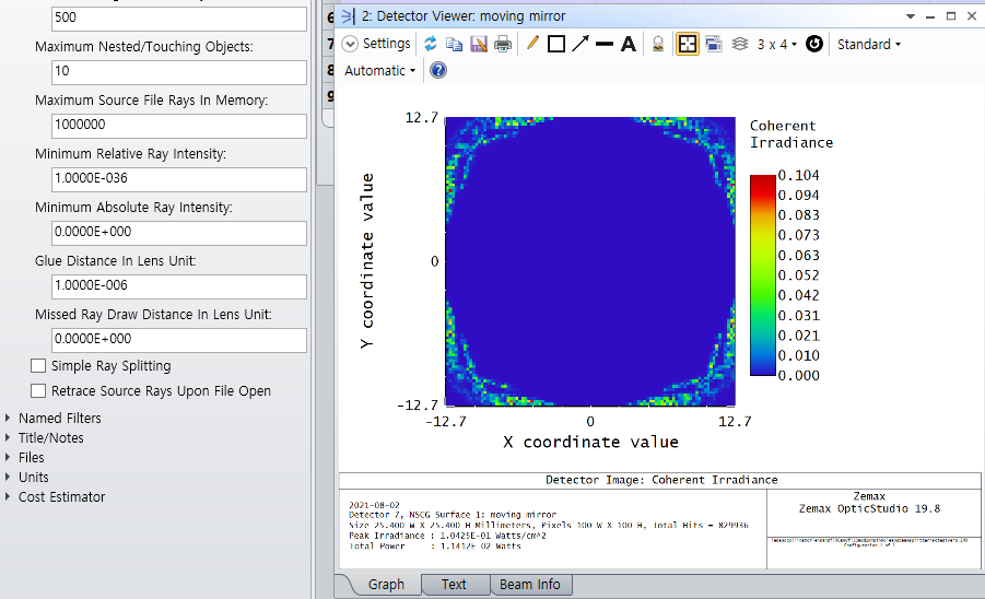
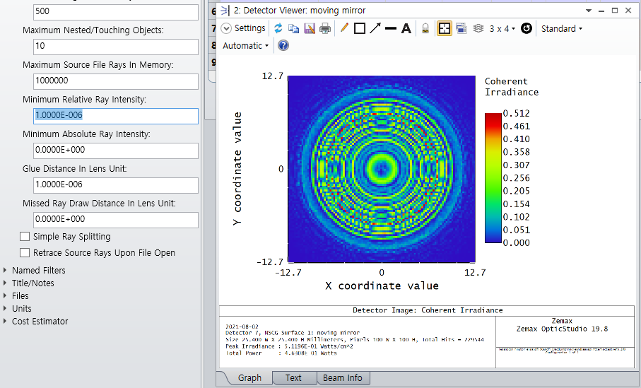
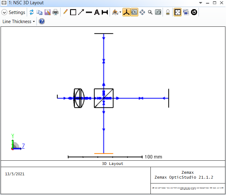
I creat Michelson interferometer by using non-sequential mode, there is no fringes in the detector(the yellow one), the fringe exsit in reference mirror plane(the right side last plane), I do not know what is wrong?


Did this topic help you find an answer to your question?

3 replies

David
Luminary
Forum|alt.badge.img+4
  • Luminary
  • 336 replies
  • May 18, 2021

Hi Wendy,

When I first started looking at your file I saw that the output detector was receiving almost no power. I began to analyze that. I changed the source to a single axial ray and saved that trace as a Ray Database, expanded in branches. Looking at the database with the Ray Database Viewer, I could see the two branches that made it to the output detector -- one from the moving mirror and one from the fixed mirror. That looked correct.

So I changed the source back to 1e6 rays and 25 degrees. When I ran a trace I saw fringes on all detectors. I have no idea what changed. I attach a ZAR file of your design as I finished with it. You can see the database analysis. It is a really good way to look at issues like this.

Also, note that I attach a ZAR format, not ZMX. You can save a ZAR by choosing that format in the fie save process. It saves all aspects of the design and is a good way to share work.

Kind regards,

David


  • Author
  • Single Emitter
  • 1 reply
  • June 7, 2021

Hi David,

Many thanks for your help. 


BBangun
  • Monochrome
  • 4 replies
  • August 2, 2021

I don't know why this happens,
In the design file, when the Minimum Relative Ray Intensity : 1.0000E-036 --> 1.0000E-006 is changed, the fringe is visible in the detector and the power is normally.


Reply


Cookie policy

We use cookies to enhance and personalize your experience. If you accept you agree to our full cookie policy. Learn more about our cookies.

 
Cookie settings