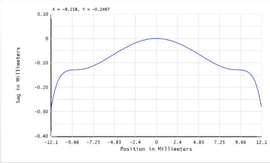
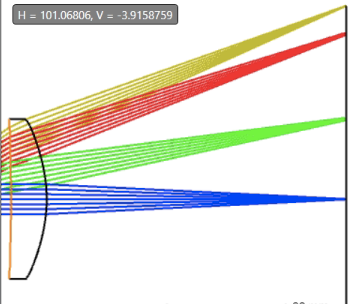
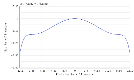
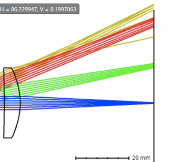
I’m relatively new to using Zemax and recently tried to optimize an aspheric lens using two extended asphere surfaces. During this process, I accidentally set the normalization radius as a variable and did not realize it until much later. I now have a negative normalization radius for both surfaces and was wondering what this means for the asphere surface? When looking at the sag of the asphere and switching the sign of the radius, nothing seems to change. However, the rays bend quite differently at the asphere surface depending on the sign. I thought this radius value was used for normalization of the coefficients, and considering all the coefficients are even, I didn’t think changing the sign would have an effect. Again, the sag does not seem to change, but the ways the rays bend on the layout change quite drastically.
Picture of sag for positive radius.

Picture of layout:

For a negative radius, sag (this looks identical to the positive case):

Layout:

For context, I am changing the norm radius of the leftmost surface.


