


I recently had this question on the support so I thought it was worth sharing.
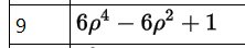
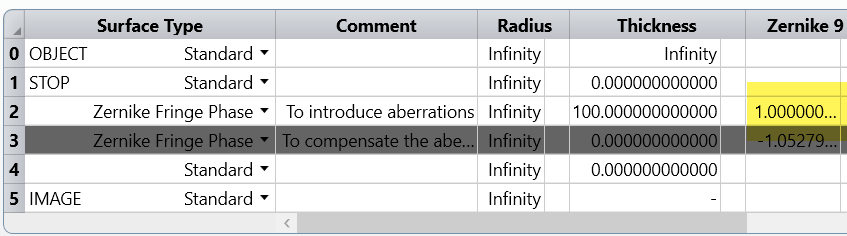
The following system contains a Zernike Fringe Phase Surface with one Zernike term Z9 = 1. This phase surface is after the STOP surface.
If we calculate the Zernike Fringe Coefficients at the image plane (Reference OPD = Absolute 2), it gives:
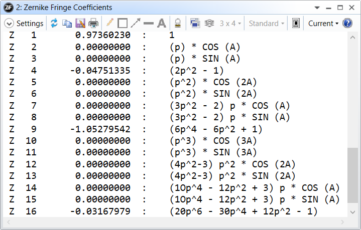
The coefficients have changed because the beam has propagated over 100mm.
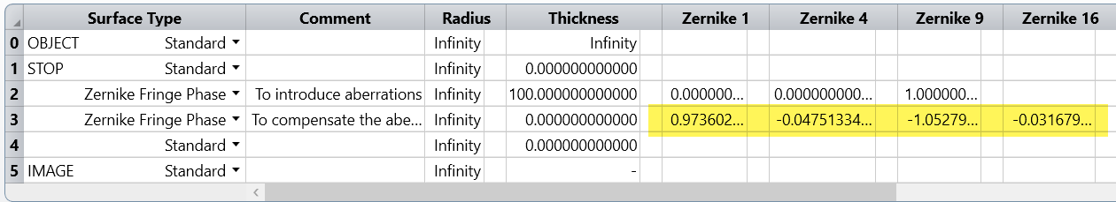
Now to compensate for these aberrations, we have defined a second configuration that contains another Zernike Fringe Phase Surface. That surface compensates the aberrations introduced by the 1st:
But if we look at the wavefront map, it is not flat:
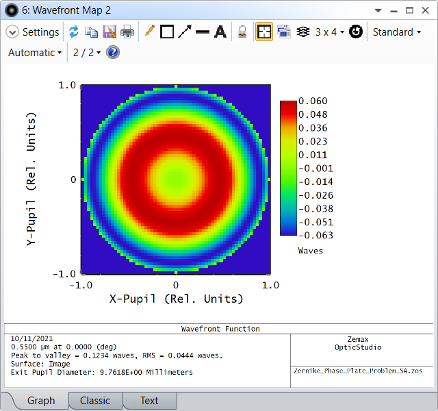
And the reason for that is that the Zernike Fringe coefficients always consider that the beam is uniformly sampled and that is ONLY true at the STOP surface.
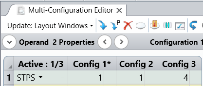
In configuration 1, the STOP is at surface 1 and in configuration 3, the STOP is at surface 4 (image surface).
Since Ray Aiming is used, the red dots (configuration 3) are uniformly sampled in the Footprint Diagram.
In comparison, it's then obvious that the blue dots (config 1) show distortion.
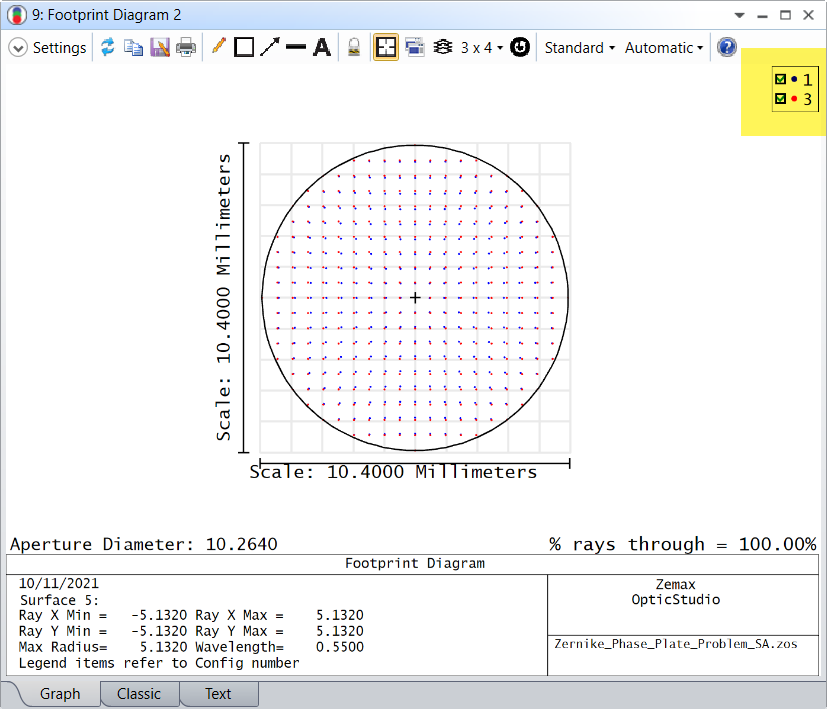
In other words, in configuration 1, we measure the wavefront on the image surface at the blue dots, but we consider the data is at red dots, which results in a wrong result.
The "Zernike Fringe Coefficients" tool always consider the sampling points are uniformly sampled.