I have tried to generate a ISO 10110 Drawing for a Biconic Lens.
Unfortunately I can only get the conic in y-direction displayed on the drawing,
then it says “see attachement”
Is there a way to generate a manufactuing drawing for a biconical lens?!
Regards,
S.E.
Best answer by Berta.Bernad
Hi Sebastian,
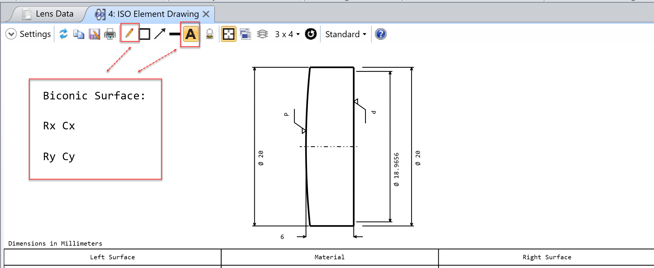
The ISO Element Drawing will only display one radius and one conic constant. So when the surface is more complex than a conic asphere, the ISO displays the surface type and asks to check for an attachment. The attachment has to be written by the user and can contain the surface equation as well as a sag map.
In the case of the biconic surface, the surface equation is quite simple and the annotations of the ISO drawing can be used to add that information:
Since the ISO drawing only displays the view of the object from the Y-Z plane, another potential workaround when designing cylindrical lenses would be to lock (or save) an ISO drawing with the current Y-Z orientation and then adjust the element model such that the former X-Z plane is defined in the Y-Z plane. You could then make and save another ISO drawing from this perspective. If needed, in the ISO Element Drawing tool’s Settings Menu there is also space under L Surf/R Surf Codes 5-6 and Material – Codes 0-2 to define an “Other” section where you can leave a note to specify the different orientations.
Alternatively, you can export your part to a CAD program of your preference using the CAD Files tool under the File tab in OpticStudio and make the mechanical drawing there. More information on the CAD Files tool can be found in the Help Files at: The File Tab > Export Group > CAD Files
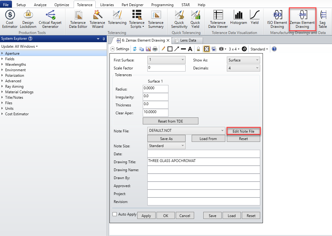
Finally, you may use Zemax Element Drawing to create drawings for cylindrical lenses with specified notes. Notes could be edited by clicking on the highlighted button.
The ISO Element Drawing will only display one radius and one conic constant. So when the surface is more complex than a conic asphere, the ISO displays the surface type and asks to check for an attachment. The attachment has to be written by the user and can contain the surface equation as well as a sag map.
In the case of the biconic surface, the surface equation is quite simple and the annotations of the ISO drawing can be used to add that information:
Since the ISO drawing only displays the view of the object from the Y-Z plane, another potential workaround when designing cylindrical lenses would be to lock (or save) an ISO drawing with the current Y-Z orientation and then adjust the element model such that the former X-Z plane is defined in the Y-Z plane. You could then make and save another ISO drawing from this perspective. If needed, in the ISO Element Drawing tool’s Settings Menu there is also space under L Surf/R Surf Codes 5-6 and Material – Codes 0-2 to define an “Other” section where you can leave a note to specify the different orientations.
Alternatively, you can export your part to a CAD program of your preference using the CAD Files tool under the File tab in OpticStudio and make the mechanical drawing there. More information on the CAD Files tool can be found in the Help Files at: The File Tab > Export Group > CAD Files
Finally, you may use Zemax Element Drawing to create drawings for cylindrical lenses with specified notes. Notes could be edited by clicking on the highlighted button.
thank you for the answer. Is there a prospect for automated drawing - generation for more complex lens types than the standard “Even Asphere” type in the furture?!.