Solved

Interpolated Pupil with Zemax

  • 22 July 2020
  • 8 replies
  • 404 views

Userlevel 2
Badge

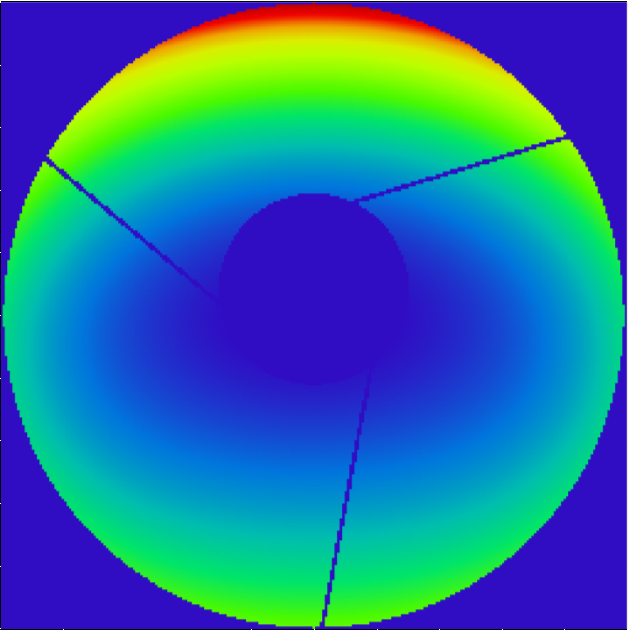
The attached file shows a wavefront with 'spiders' from a telescope.

These spiders require a very high pupil resolution for a well converging PSF calculation. But I need to calculate a huge number of PSFs and have to restrict the pupil sampling because of computing time.

Is there a possibility for 'Edge Smoothing' in Zemax? I mean a kind of 'apodization' of the spiders that yields a smooth transition from bright to dark that improves the convergence?


Additionally: The spiders and the inner obscuration are (as usual in telescopes) not in the plain of the aperture stop. Is the Zemax PSF calculation (FFT or Huygens) still valid?


bild1.png
icon

Best answer by Mark.Nicholson 22 July 2020, 20:32

View original

8 replies

Userlevel 7
Badge +3

Hey Christoph,


Sure, you could add a Slide object with a suitable bitmap image on the pupil plane, or use a user-defined surface to give the apodization you want. A slide object will give you an easy way to access 8-bits per color plane of smoothing, and a user defined surface will give you anything you can think of.


BUT


we have tried many things over the years to improve sampling at the edges of circular pupils and general obscurations and nothing has worked in general as well as simply turning up the sampling. That's not to say they won't work in your specific case, but we've put a lot of work into this over the years and have reluctantly come to the conclusion there's nothing smarter in general than just upping the sampling.


Both Huygens and Fraunhofer (FFT) diffraction calculations consider the pupil to have had a shadow cast on the pupil, and do not consider any diffraction from the aperture to the exit pupil. The diffraction is all in going from the exit pupil to the image. To consider diffraction in general, as in going from surface a to surface b say, use POP. Of course, sharp apertures are exactly what POP needs, diffraction comes from the edges.

Userlevel 4
Badge +1

Hi Christoph,


Thank you for your post and glad we meet again here in the forum!


This is an interesting question you raised. I can think of two ways in OpticStudio to do apodization. First is the Apodization factor setting in the System Explorer. However, that's a radial apodization, meaning intensity as a function of radial coordinates I(r). In your case, if i understand it correctly, you are trying to 'smooth' out the edge of the spider arm in angular direction. So this option won't work. The second option is to use user defined apodization. OpticStudio supports user defined apodizations on any surface, rather than just the entrance pupil. User defined surface apodizations are implemented using the user defined surface type constructed using DLLs. There is one sample DLL US_FILT8 which models a soft edged rectangular aperture. In this sample DLL, the Transmission varies smoothly from 1 to 0 over twice the distance defined by the DelX and DelY distances from the aperture boundaries. I thought you might be able to use this to model each one of the 3 rectangular spider arms. However, it'll require some adjustment from this sample DLL. The spider arms are obscuration not transmitting, and also you need 3 of these rectangular apertures. So this might require some effort to set up. And it's hard to say if it'll in fact help PSF converge better. If you wanna give this a try, you could probably start with modifying the DLL and start with a single arm to see if it makes any difference.


The FFT and Huygens PSF computations use geometric ray based wavefront at the exit pupil to compute PSF on the image plane. This is the so called single step diffraction analysis where only the diffraction effect propagating from exit pupil to image plane is considered. Everywhere else in the system, rays are used to model beam. In that sense, it's ok to have spider obscuration not at the Stop surface. You just need to keep in mind that any diffraction effect, for example those caused by aperture clipping beam earlier in the system, will not be modeled since rays are used to propagate and rays don't interfere with each other. 


Let me know if this answers your question or if you have any other questions. 


Best regards,


Hui


Userlevel 4
Badge +1

ah, I posted my reply above without realizing Mark has already replied to your post! Thank you Mark! :)


I agree the Slide object might be an easy way to 'apodize' than having to create your own complicated spider soft edge obscuration.


Best regards,


Hui

Userlevel 2
Badge

Hi Marc and Hiu (yes, glad to meet you again :-)),


thank you for these valuable informations! They are really helpful for me.


Concerning the smoothing of edges, I actually have no own experience. It seemed kind of straight forward to me that it should help. Is it the problem how to exactly distribute the grey scale pixels to better represent the object? Or would you say smoothing by grey scaling is simply a different thing than increasing the resolution and can in general not replace it? Or any insight, why it is not so helpful?


A 'single step diffraction analysis', this is a very pregnant and accurate formulation! I was searching for this wording, thank you 🙂.


We 'do not consider any diffraction from the aperture to the exit pupil.' My understanding was that in the pupil planes, there is no diffraction. There are sharp edges of the aperture stop. And this is a property that the single step diffraction uses. But in a rigorous sense, this is not true? Because the image of the aperture is also afflicted by diffraction, as every optical image?


My understanding was this:

The wavefront is geometric ray based. Geometric optics is a good approximation as long as the lateral WF changes are slow in units of the WL, which is almost always the case, except for the aperture stop, where the lateral WF has a suddan edge.


Therefore,  geometric ray tracing is valid in the pupils, as there is 'no' diffraction in the pupils... But I just learned, there is diffraction in the pupils, but only marginal?


So, if there is no vignatting at different planes, that would cause strong diffraction effects and if we assume all optical elements to be quite large compared to the ray optical beam diameter, then we can consider the aperture stop to be the only plaine that causes diffraction. Is this correct?


But now my question:

My exit pupil maps the aperture stop that restricts the outer diameter of the beam. But the inner obscuration and the spiders are in totally different plains. So the pupil is not a pupil for these features. Diffraction in my case happens in different plains. Is it still justified, to use the single step diffraction? Or is it necessary to consider these multiple diffractions with POP? At the end, I am interested in the PSF.

Userlevel 7
Badge +3

Hi Christoph,


These are some excellent questions. Let's start off without any obscurations in a rotationally symmetric imaging system. 


Think of relatively low field angle, unobscured system, in which only the system aperture stop defines the bundle of rays that are traceable. Since the exit pupil is the image of the stop, it has a sharp edge too. So, there is an infinite slope to the energy in the wavefront at the edge of the pupil, and it is this infinite slope that causes energy to diffract as the light propagates from pupil to image.


The other surfaces do not contribute diffraction, as their edges are never illuminated and you can think of them as being infinite in size compared to the wavefront, or at least so large that there is no truncation of the beam as it passes through the surface. Only the stop surface clips the beam


Now as you increase field, aperture and wavelength range, the image of the stop becomes aberrated, and so loses some of its sharpness. The boundary region of the pupil will become blurry, and so diffraction effects become less noticeable. Diffraction is generally only important in systems with less tham lambda/4 PTV OPD forthis reason: geometric aberrations start to dominate after this, and the imaging performance is no longer limited by the sharp-edged wavefront in the exit pupil.


Now, let's go back to the diffraction-limited system, and imagine adding some other obscurations to the beam, on the stop surface. Again, since the entrance pupil, exit pupil and stop are all images of each other, this results in a sharp image of the obscuration on the exit pupil. Sharp edges cause diffraction, and so we can compute the PSF at the image plane as the FFT of this distribution.


Now, move the obscuration onto another surface, away from a pupil plane. This now affects the illumination of the pupil, but this obscuration is not imaged sharply onto the pupil plane. Look at the footprint diagram at the exit pupil position to see what I mean. 


So, how important is this shadowing by an intermediate obscuration? Well, it will be less important than having the obscuration at a pupil plane, but it will still reduce lens resolution compared to the unobscured surface. Using the Huygens or Fraunhofer (FFT) diffraction calculations we still compute the shadowing on the exit pupil without allowing for diffraction from the edges of the obscuration in propagating from the obscuration to the pupil plane. If the obscuration is large compared to the wavelength, then that's probably a good approximation. But there's only one way to know for sure...


POP eliminates all this pupil-imaging stuff and does a raw, surface by surface propagation of the wavefront through the system, accounting for diffraction in the propagation from every surface to the next, then from that to the next etc so diffraction effects accumulate. The final PSF is the accurate (when adequately sampled) total system sum. The end result, however, if often anti-climactic since the diffraction from arbitrary apertures is not in general focused on the image plane in any way. So that diffraction tends to wash out except in cases like Talbot imaging, zone-plate diffraction, or diffractive optics. But, the only way to know for sure is to do the POP test and compare to the Huygens PSF. There's no way to answer the question in the general sense: you have to build the model and try it to see.


And this is also why our experiments with blending apertures never paid off. Diffraction is caused by sharp edges causing illumination to be sharp-edged. Light diffracts from sharp-edged distributions. The softer you make the edges, the less diffraction there is. You can make these things work in special cases where you know there is an analytic solution (circular pupils will give Bessel functions, rectangular will give sinc functions and so on), but for the general case you want the sharpest possible edges, which means the highest possible sampling.


I hope that helps. Bottom line: you need to increase sampling to make sure your sampling is adequate.


- Mark

Userlevel 2
Badge

Thank you Mark, for your support! I would like to comment as follows:


'Since the exit pupil is the image of the stop, it has a sharp edge too. So, there is an infinite slope to the energy in the wavefront at the edge of the pupil, and it is this infinite slope that causes energy to diffract as the light propagates from pupil to image.'


If we want to argue in a principle sense at this point, then the pupil is not sharper than an optical image can be, which is diffraction limited. I wonder, if this is already - at least in principle - a first approximation?


And although diffraction is most obvious at sharp edges, it is a basic wave-phenomena that is always present.

E.g.:

- A Gaussian laser beam shows at least the beam divergence due to diffraction - without sharp edges.

- A aperture stop with Gaussian Appodization would not prevent from diffraction, but just change the shape of the PSF to a Gaussian shape.

- And the 'ray based wavefront' is an approximation, because rays propagate independent of each other through the system while waves are laterally coupled. Therefore, wavefronts change the shape during propagation. I would consider this also as a consequence of diffraction. And it happens already before a stop is reached.


'Now, move the obscuration onto another surface, away from a pupil plane. This now affects the illumination of the pupil, but this obscuration is not imaged sharply onto the pupil plane. Look at the footprint diagram at the exit pupil position to see what I mean. '


Well, the footprint always looks sharp, doesn't it?


'So, how important is this shadowing by an intermediate obscuration? Well, it will be less important than having the obscuration at a pupil plane, but it will still reduce lens resolution compared to the unobscured surface. '


Yes, the inner obscuration of this telescope (it is the space telescope 'Euclid' by the way) is without doubt considerable. But is the impact really always less important if the obscuration is away from the pupil plane?


'If the obscuration is large compared to the wavelength, then that's probably a good approximation.'


Yes, I think this is in principle the important measure 🙂. Assume, we put an optical lattice somewhere in the optical path. Ray optics will surely not yield a meaningful result. But an optical lattice in the pupil plane, this may work, provided the pupil is sampled fine enough.


So it seems that a POP evaluation will make sense in my case.


Thanks again and best regards,

Christof.

Userlevel 7
Badge +3

Yep, you're going to have to do a POP analysis to settle this. Just one point:


If we want to argue in a principle sense at this point, then the pupil is not sharper than an optical image can be, which is diffraction limited. I wonder, if this is already - at least in principle - a first approximation?


It's a very deep approximation for sure. We assume a point (not Gaussian) source, which radiates a spherical wave. That wave then gets truncated at the stop surface, so it now has a sharp edge. The stop gets imaged to the pupil plane, which therefore also has a sharp edge. The pupil plane is the only place in the system where the wavefront has this sharp edge, and to that extent is free of diffraction. The image plane is in principle infinite in extent, because of the diffraction from the edge of the pupil.


This all comes down to the approximations we make for ray tracing in imaging systems. For your system, you're going to have to validate that with your obstructions for (a) imaging performance and (b) stray light. Good luck! 

Userlevel 2
Badge

Thank you Mark and Hui. Take care!

Christof.

Reply