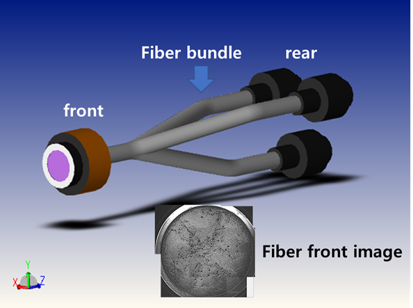
I would like to simulate bent fiber bundle beam divergence which include almost 8,000 single mode fiber. but I am wondering if it is reasonable to model a bundle of fibers by inputting 8,000 single fibers.
Also, for analysis, after dividing the fiber front modeling(objective lens part) and the fiber rear modeling(condensing lens part), is there any problem if the wavelength distribution incident on the fiber front part is applied to the source of the fiber rear modeling?
Thank you
Best answer by Angel Morales
Hi Byeong,
Thanks for the added detail and clarification!
I do wonder if you’d be able to get a sufficiently approximate performance, then, from a much simpler geometry (large, cylindrical, reflective tubes which can direct the input light), since you’re mostly interested in the angular output of the fiber bundles? It might not be required to define a UDA file to mimic the 8000 smaller fiber output diameters, as this would be more of an effort to observe the spatial pattern rather than the angular characteristics of the bundle. Is this an approach that you’ve tried already?
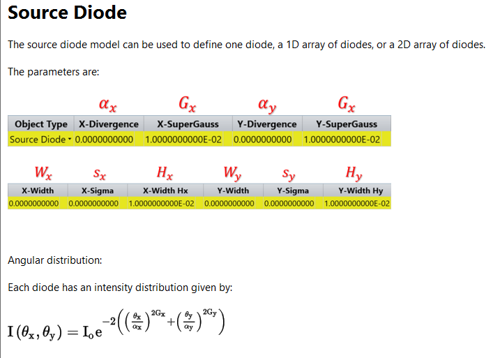
Also, regarding your LCD/OLED modeling, we do have an article here which exhibits one approach to modeling an LCD display: How to model an LCD backlight – Knowledgebase (zemax.com). The LCD article demonstrates defining a backlight source that is guided out through the rest of the display geometry. Since OLEDs are effectively sources that are arrayed along the screen itself, I think using the Source Two Angle object is a good way to characterize the emission of an OLED screen, since you can size the source to any rectangular or elliptical shape you’d like. We also have the Source Diode object, which can take in various parameters to define the angular and spatial emission pattern -- you can read more about the object in our Help Files at “The Setup Tab > Editors Group (Setup Tab) > Non-sequential Component Editor > Non-sequential Sources > Source Diode ”:
While you do have the option to array these sources in a 2D pattern, depending on how many diodes you define, it might be less computationally intensive to have a single, large emission area rather than many smaller diodes.
Thanks again for your time -- let us know your thoughts here!
I think modeling a bundle of 8000 single mode fibers would be very computationally taxing on the simulation. You might be able to leverage the Array object to generate the entire bundle of single mode fibers from a single fiber geometry. If I understand correctly, the 8000 fibers are split three ways, making each arm ~2666 fibers? So, you might use something like three Array objects to generate each different arm of the fiber bundle. Again, with that many arrayed objects, I do think the ray trace might take some time to complete. Also, this does assume that each fiber has the same bend radii across the bundle (for each Array object), which I am not sure is the case with your specific geometry.
Alternatively, do you know if you’d be able to achieve roughly the same output with a simpler geometry, such as three reflecting cylinders in the same setup as your fiber bundle? Are you specifically trying to obtain a result like the “Fiber Front Face” image in your post, but just for the rear side instead? What are you specifically trying to evaluate after your condenser optics? I ask because if you’re mostly concerned about the angular distribution of light after the condenser optics, then it might be a valid enough approximation to use the reflecting cylinders. However, if you’d like to visualize the rear bundle face itself, this would be tougher to do and would require something like the 8000 fibers being defined, or perhaps a user defined aperture that can mimic the 8000 “apertures” of the fibers (though this would likely require a very detailed .UDA file as well).
How do these thoughts work out for you? Let us know -- I’d also be interested to see if anyone else has any ideas!
For the actual fiber bundle does the bending radius is not uniform, in the form entangled in a bundle. and purpose of the simulation is to obtain the wavelength distribution for each angle incident on the photo diode in the path of objective lens -> fiber -> condenser lens -> PD. The fiber front face in the post is just an example to show 8000 fibers and beam angle distribution characteristics in the fiber rear are important. as your mentioned, perhaps user defined aperture that can mimic the 8000 “apertures” of the fibers seems very difficult…
(additional question) In zemax NSC, How to Model Mobile Phone Display panel?(OLED, LCD) (I used source two angle, but It is correct?)
I do wonder if you’d be able to get a sufficiently approximate performance, then, from a much simpler geometry (large, cylindrical, reflective tubes which can direct the input light), since you’re mostly interested in the angular output of the fiber bundles? It might not be required to define a UDA file to mimic the 8000 smaller fiber output diameters, as this would be more of an effort to observe the spatial pattern rather than the angular characteristics of the bundle. Is this an approach that you’ve tried already?
Also, regarding your LCD/OLED modeling, we do have an article here which exhibits one approach to modeling an LCD display: How to model an LCD backlight – Knowledgebase (zemax.com). The LCD article demonstrates defining a backlight source that is guided out through the rest of the display geometry. Since OLEDs are effectively sources that are arrayed along the screen itself, I think using the Source Two Angle object is a good way to characterize the emission of an OLED screen, since you can size the source to any rectangular or elliptical shape you’d like. We also have the Source Diode object, which can take in various parameters to define the angular and spatial emission pattern -- you can read more about the object in our Help Files at “The Setup Tab > Editors Group (Setup Tab) > Non-sequential Component Editor > Non-sequential Sources > Source Diode ”:
While you do have the option to array these sources in a 2D pattern, depending on how many diodes you define, it might be less computationally intensive to have a single, large emission area rather than many smaller diodes.
Thanks again for your time -- let us know your thoughts here!
Thank you very much for your suggestion. An additional question about cell phone displays was to define, not model, thank you for explaining it despite my mistakes.
I'll tried to the simpler geometry fiber bundle (large, cylindrical, reflective tubes which can direct the input light) you suggested.