Hi Zemaxers


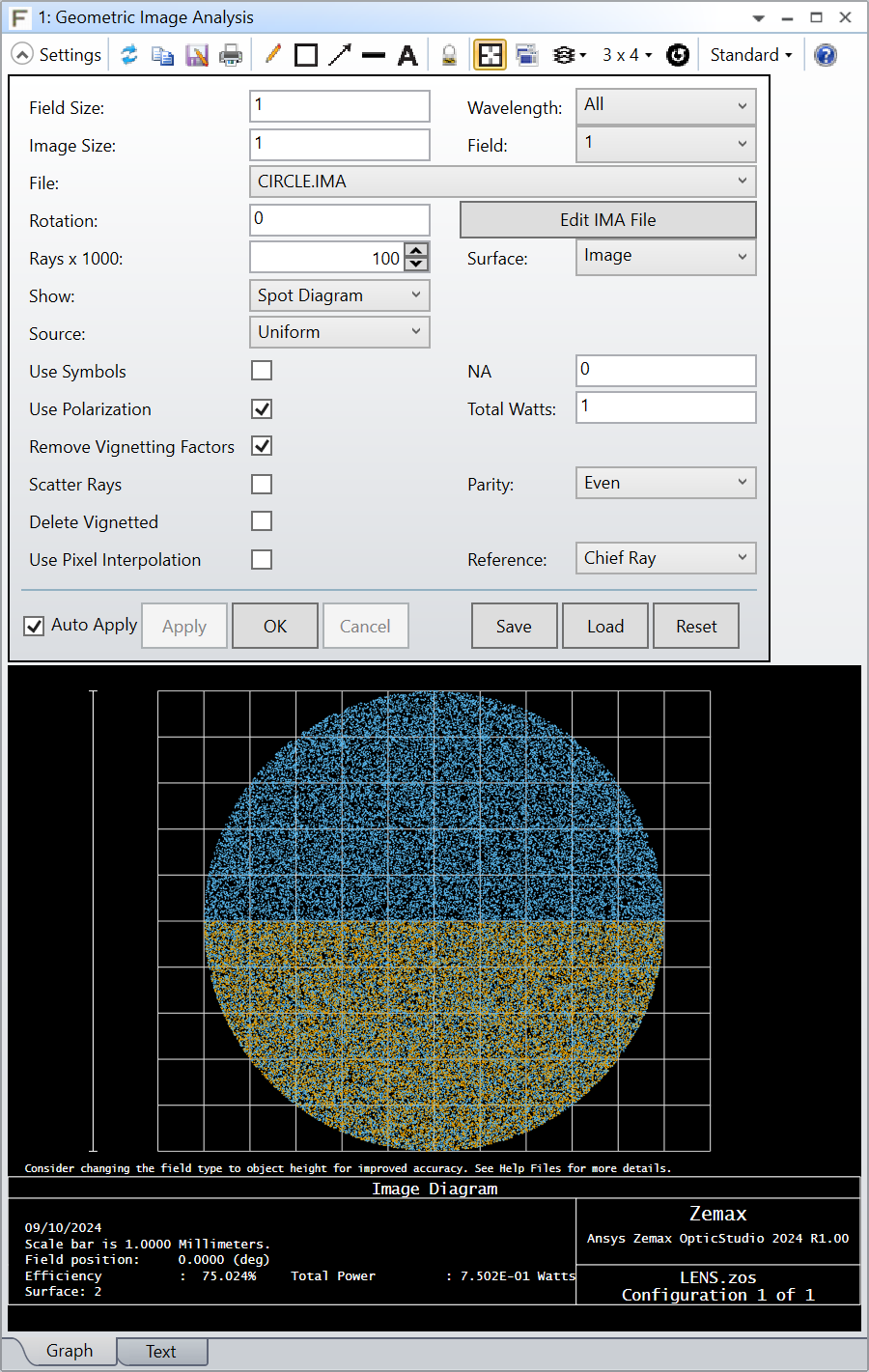
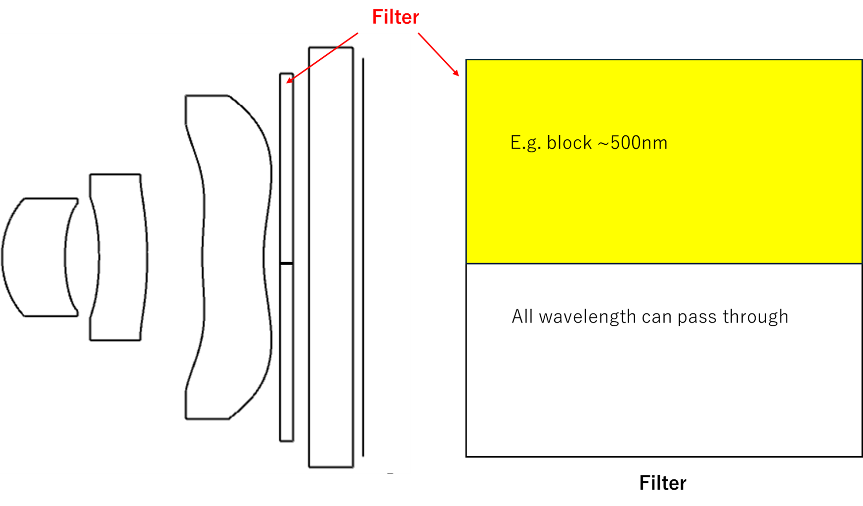
 In sequential mode, how to set a filter like below? or is it possible to set such a layout in sequential mode?

The filter has two parts, the upper area blocks 500nm and below, and the other half is OK for all wavelengths.


Best regards

YANG

Hi Yang,

In sequential mode, a ray cannot “skip” a surface so you cannot simply have a single configuration with a 500nm band pass filter that is decentered.  However, you can split your image plane into 2 halves with multi-configs, use a TABLE coating to create a cutoff filter and then use a number of paired down analysis which can merge the 2 configurations back together (Spot Diagram, Footprint Diagram, Geometric Image Analysis, Huygens PSF, Huygens MTF).

However, the better approach would be to create a User Defined Surface and leverage the UD->rel_surf_tran property.  In the User Data structure, you have access to the ray’s XY coordinates (UD->x and UD->y) and in the Fixed Data structure, you have access to the ray’s wavelength (FD->wavelength).  So the pseudo code in case 5 of the UDS would look something like this:

case 5:
if (UD->y >= 0.0 && FD->wavelength >= 0.5)
{ UD->rel_surf_trans = 0.0; }

if (FD->cv == 0.0){
if (Refract(FD->n1, FD->n2, &UD->l, &UD->m, &UD->n, UD->ln, UD->mn, UD->>)) return(-FD->surf);
} else {
/* not a plane, copy code from UDS example for snell’s law refracting */

}
break;

There are 8 different UDS filter examples in the Zemax\DLL\Surfaces folder that can help you get started.

P.S. If you can use non-sequential, I would suggest doing that.  This is a trivial problem in non-sequential mode.

Hi Michael

 Thanks for your reply. I think the User Defined Surface can make it.

I will have a try

 Thanks again!


Yang


Hi Yang,

In sequential mode, a ray cannot “skip” a surface so you cannot simply have a single configuration with a 500nm band pass filter that is decentered.  However, you can split your image plane into 2 halves with multi-configs, use a TABLE coating to create a cutoff filter and then use a number of paired down analysis which can merge the 2 configurations back together (Spot Diagram, Footprint Diagram, Geometric Image Analysis, Huygens PSF, Huygens MTF).

However, the better approach would be to create a User Defined Surface and leverage the UD->rel_surf_tran property.  In the User Data structure, you have access to the ray’s XY coordinates (UD->x and UD->y) and in the Fixed Data structure, you have access to the ray’s wavelength (FD->wavelength).  So the pseudo code in case 5 of the UDS would look something like this:

case 5:
if (UD->y >= 0.0 && FD->wavelength >= 0.5)
{ UD->rel_surf_trans = 0.0; }

if (FD->cv == 0.0){
if (Refract(FD->n1, FD->n2, &UD->l, &UD->m, &UD->n, UD->ln, UD->mn, UD->>)) return(-FD->surf);
} else {
/* not a plane, copy code from UDS example for snell’s law refracting */

}
break;

There are 8 different UDS filter examples in the Zemax\DLL\Surfaces folder that can help you get started.

P.S. If you can use non-sequential, I would suggest doing that.  This is a trivial problem in non-sequential mode.


Hi Michael and zemaxers,

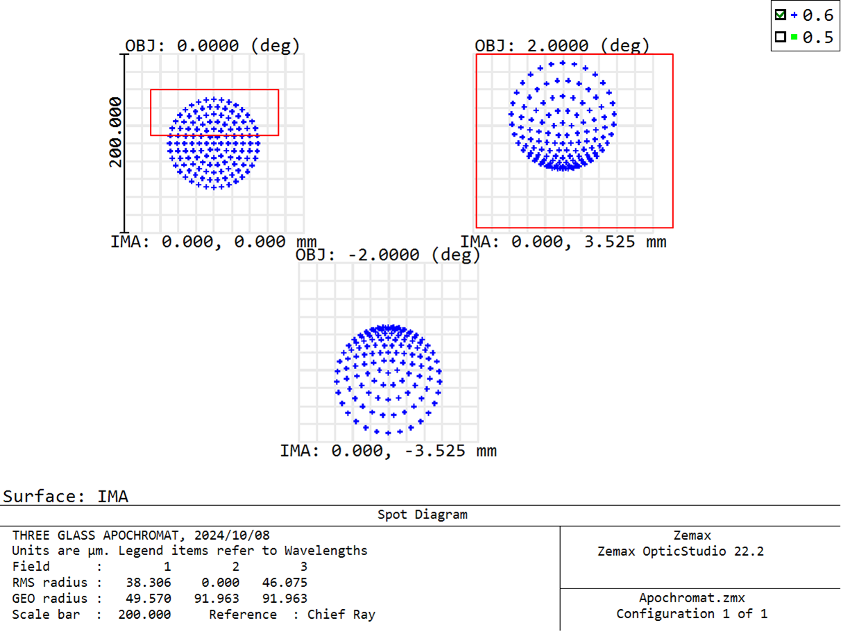
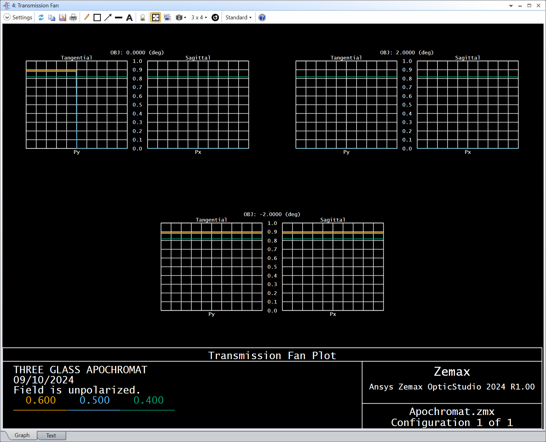
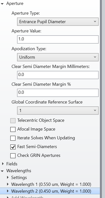
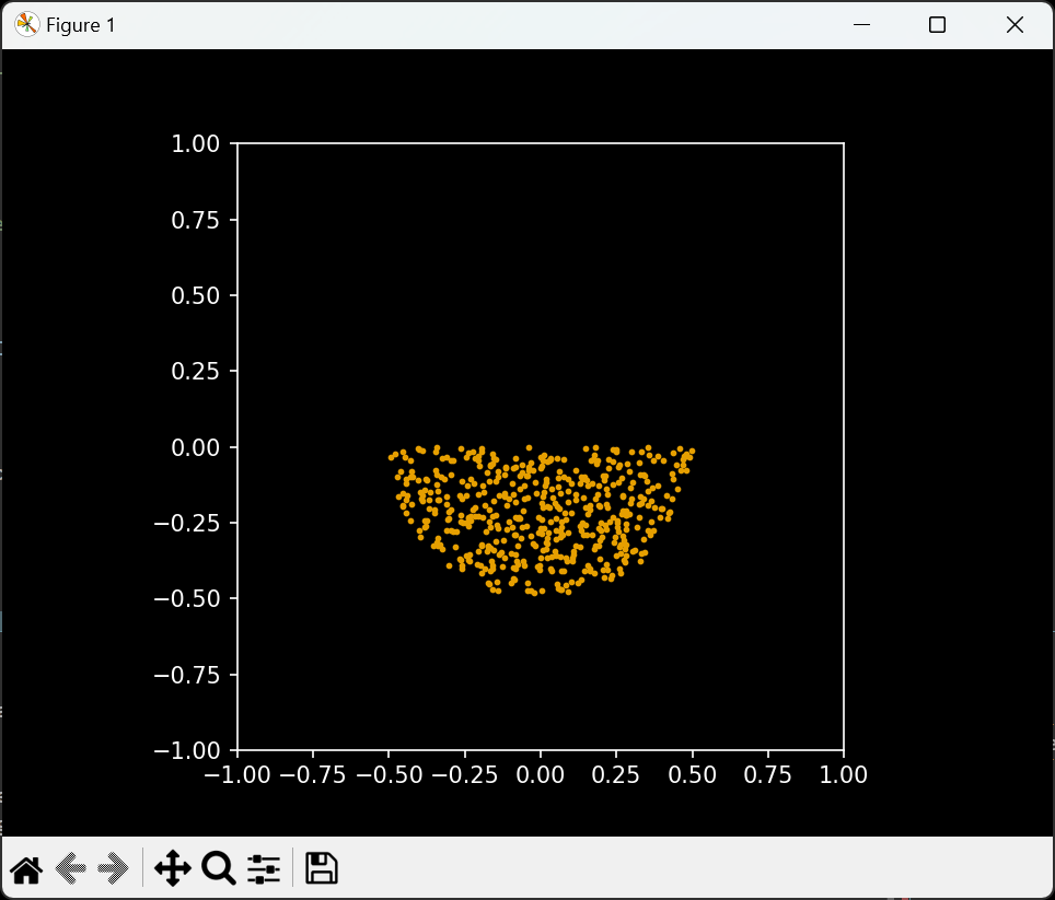
 I have tried the UDS but got the result not as I thought

y>=0 && wave >=0.5   rel_surf_tran =0

there shall be no spot in red rectangle area of the pic below, right?

I am just wondering where I am wrong .


Would you please have a check with my file?


Thanks


Yang


Reply