Hello everybody!


I'm working with Zemax Opticstudio to design a micro-optical system which would allow me to couple efficiently a laser-diode to an optical fiber. (I'm a poorly self taught zemax user...)


Due to mechanical and spatial requirements, I'm not able to use regular lenses to perform the fiber coupling, but instead I have to use a periscope to divert my light rays from the source to the fiber.


Specifically, the periscope should receive the rays from the source (propagation along Z axis), reflect them upwards along the Y axis (+90deg fold), and then reflect them once again backwards (+90deg fold), so they'll back-propagate towards the fiber (propagation along -Z axis).


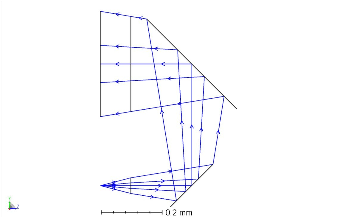
The periscope will be a single optical element, made with precision molding. Therefore the rays are emitted from the source, they travel in air and then enter the periscope (surface_1). From surface_1, they propagate in a dielectric material to the first mirror (surface_2) for a thickness_1, they get reflected upwards towards the second mirror (surface_3) for a thickness_2. Then they get reflected backwards from surface_3 to the exit of the periscope for thickness_1. After they exit the periscope the propagate in air towards the optic fiber input (see pic[1]). (All thicknesses, diameters etc are below 1mm)


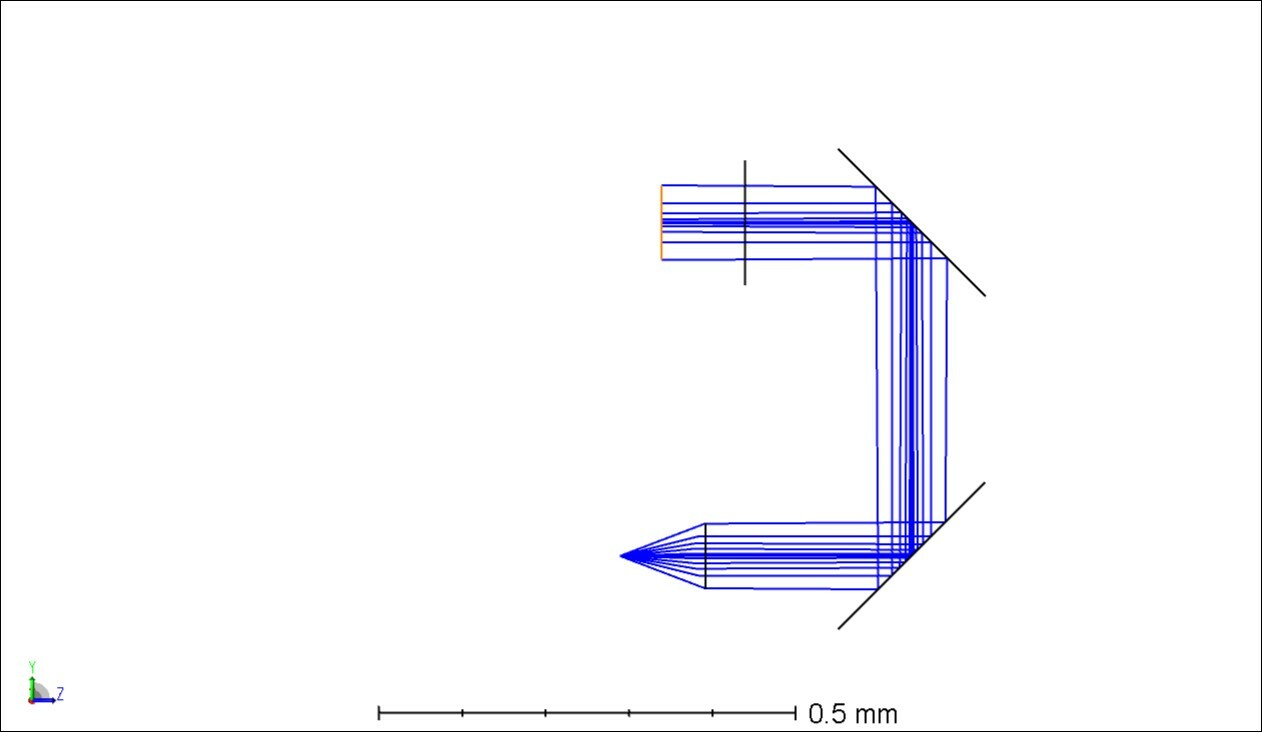
Ideally the simplest system consists of the two reflecting surfaces, which I choose to be Biconic-Zernike mirror surfaces with a simple metal coat (see pic[2]).


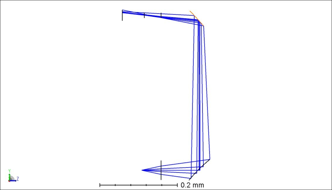
An alternative design, would introduce an additional refractive surface at the periscope entrance to allow control of more degrees of freedom, and higher coupling efficiency (see pic[3]. here I have firstly optimized the entrance surface to colimate the rays on their way to surface_2)).


Such a system is very easily designed in Zemax Optic Studio, and the optimization should be performed without great difficulty using the POPD optimization operand, in sequential mode.


Unfortunately, my system refuses to converge to a good solution, regardless the many different approaches employed. 


e.g. I've tried to use other surface types, I've changed the merit function criteria, I introduced the periscope as a non-sequential component, and more.


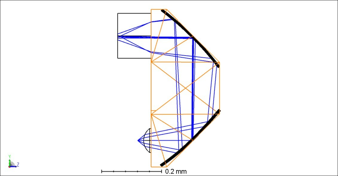
The system keeps refusing optimization, and more annoyingly will deflect the rays to random directions, away from the optic fiber optical axis (e.g. pic[4]).


I'd like to ask you therefore for some inputs that would allow me to move on.


Do you know of a better optimization approach for such a system?


How can I force the rays to converge towards the fiber, keeping the chief ray parallel to the fiber optical axis?


In general any suggestions/solutions would be much appreciated.


Thanks a lot!


(A few more details about the system: The aperture type is set to object space NA, at 0.25. Gausian apodisation 1. Wavelength 638nm. Ray aiming off. Refractive index in the range 1.51-1.56)

Hi Jonas! Thanks for your question here.


I've taken a look at your file, and in general, I think you've got some good starting points, but the issue in optimization stagnation could be due to a number of factors.


  1. You mention using the POPD operand, but the file you shared was in a bit of a 'starting' state for the design. While your last two images show some changes after optimization, I wonder if the inclusion of the POPD operand at a starting point in your design might be contributing to some difficulty in optimization. The reason I mention this is because POP itself is very dependent on having proper analysis settings for adequate sampling of the irradiance and phase data on a surface-by-surface basis (for some more information on this, we have a 3 part Knowledgebase article series that starts here). So, if there is a significant enough change during optimization to require a change in POP settings, you'll be adjusting your system based on non-relevant data. It might be worth optimizing just based on the ray information at first,, such as spot size (somewhat like the article here) before you move on to including a more complex analysis like POP.


  2. You've also mentioned that you tried different surface types, different merit functions, etc. Again, since I was able to see the starting point, but not really the variables you exposed for each surface, it's hard to comment on what could be the case. However, I have seen and heard that if we allow too many higher-order terms to vary initially, the optimization can be 'stunted' since the solution space becomes increasingly more complex (and thus, harder to determine how to adjust the variables for an improved merit function value). It might be worthwhile to expose a few, lower-order terms, and gradually walk up to higher-order terms as needed to get the performance you need. Still, optimization is a bit of an art and a science, so you still might find yourself changing surface types, criteria, etc., until you progress toward a design that fits your needs.


  3. Lastly, for things like controlling the location of your spot after the periscope, you might find some use including some boundary operands like CENX/CENY -- these operands will report the location of a spot's centroid per field point. So, if you find your axial spot 'walking' up the image plane, including these operands along with some boundary operands like OPLT/OPGT (OPerand Less Than/Greater Than) can control the spot's position on the last surface -- you can read about all the available optimization operands in our Help Files at 'The Optimize Tab (sequential ui mode) > Automatic Optimization Group > Merit Function Editor (automatic optimization group) > Optimization Operands (Alphabetically)'.


Please let us know how these thoughts work out for you. Thanks again for your question here, and best of luck!


~ Angel


Hi Angel,


Thank you for your feedback.


I'll work on it and I'll let you know how things work out.


Reply