Solved

How to make parametric simulation of non-sequential model.

  • 17 October 2019
  • 6 replies
  • 139 views

Hello,


I would like to solve a parametric non-sequential model, where I change certain geometrical parameters.


At the moment I do this manually step by step, saving one model for every parameter setting.


I'm sure there is something that allows for automatic batch calculation of these parameters. Best would be to have all solutions in one model and the ability to switch between these results.


I know there are the options Slider, MC Editor or ZPL-Macros. However, In Slider I cannot set the increment between the parameter steps, which gives me way too much solutions I don't need and which take lots of time to calculate.


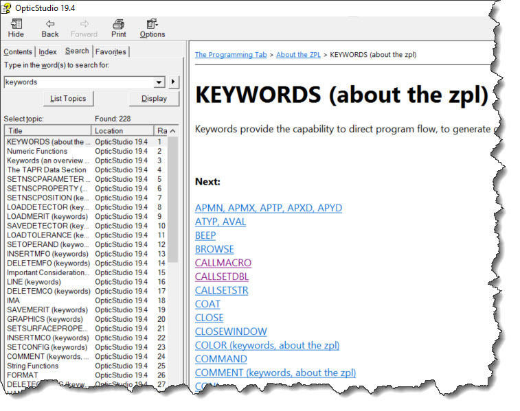
For MCEditor and ZPL-Macros I could not find any useful tutorial allowing me to learn these topics in rather short time.


I would really appreciate if someone could give me a starting point, how to solve this problem with a rather handy solution.


Thank you for reading,


Clemens
icon

Best answer by David 17 October 2019, 21:02

View original

6 replies

Userlevel 6
Badge +4
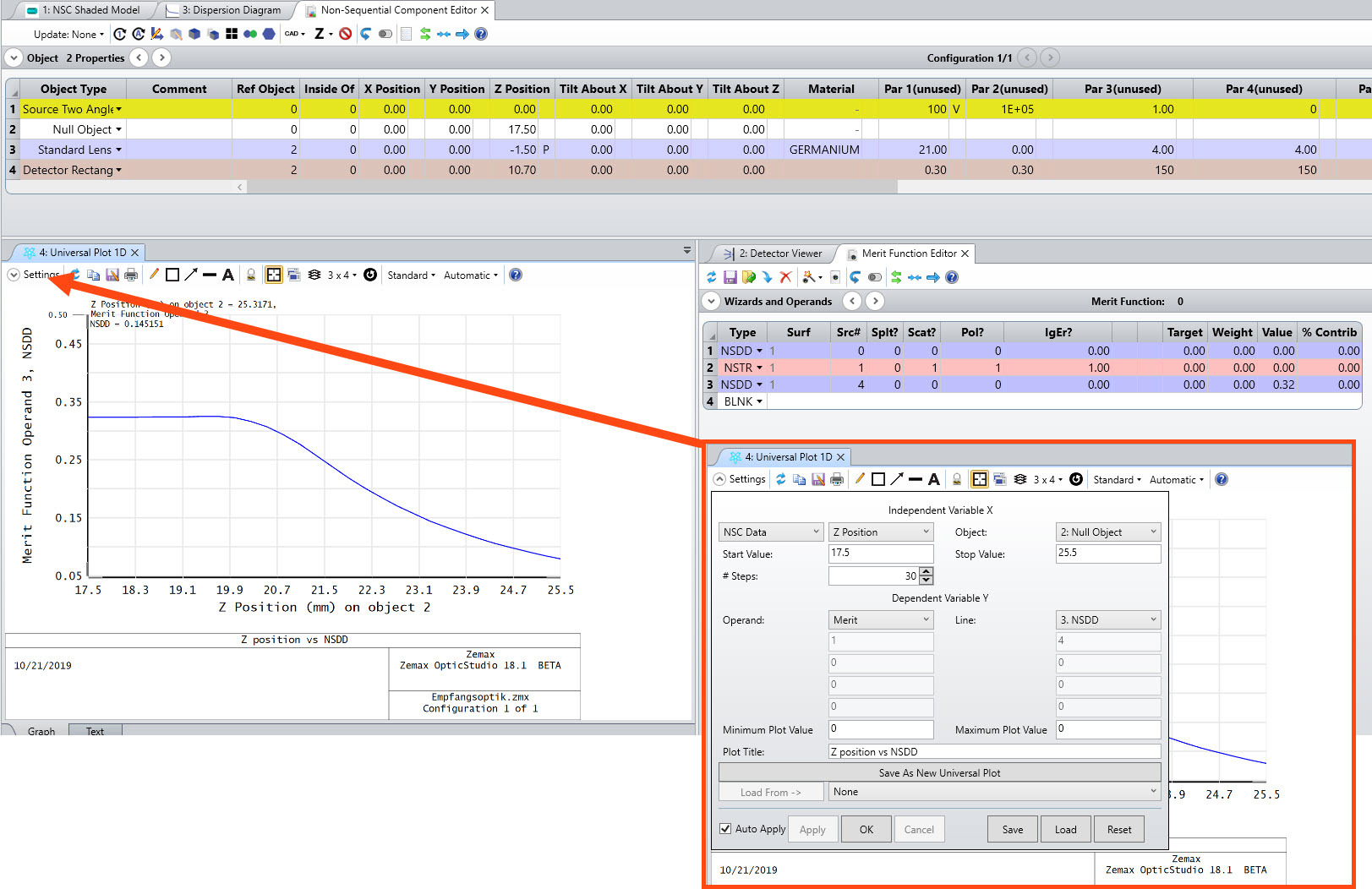
If what you need is a numerical value, like one which could be calculated in the merit function, you could use Universal Plot under the analyze tab. This allows you to generate a graph based on varying a parameter with a prescribed stepping, and to obtain the data that the graph is based on. For more complex requirements I would use ZOS-API and Mathematica -- or Python, Matlab, C#, C++.
Userlevel 4
Badge +3
Hi Clemens,


I think that both the Multi-Config Editor (MCE) or a ZPL macro could serve your need... using MCE would allow you to perform analyses on the system that considers all configurations at once. As a general statement, this tends to be a more important consideration in sequential models than non-sequential ones. Use of a ZPL macro could allow you to set up a loop of the values you'd like your parameters to take, automate a raytrace, save results, and export them for further analysis. Another option with ZPL would be to automate creation of a series of .ZMX files, each containing one of the parameter settings.


For learning MCE, we do have a sequential tutorial in the Getting Started Guide (on the Help tab of OS), but we don't have a non-sequential tutorial. The principles are the same, but the actual MCE operands will be different for non-sequential mode.


I noticed that you do have a supported license, so if you opened a support ticket, the team can likely help guide you on exactly what you need or possibly even create a sample macro, especially if you can share your file and give a bit more detail about what parameter needs to change and how you will go on to analyze the system.

Dear Alissa, Dear David,


thank you for your comments.


@David: Universal plot really looks like a simple way to acquire results. However I'm already stuck when defining the dependent component.

What I would like to do for example is to plot the total power received by some detector versus some distance. I do not see how to get that.


Maybe you can provide some further explanations.


@Alissa: Indeed I already did this tutorial you suggested. However I got immediately stuck when going to NSC mode. For example when I want to change geometry parameter using PRAM I can only select three surface independent on how many objects I define.

Also I'm not sure how to calculate the different configuration in a sequence. I wouldn't want to start a model for every single parameter step by hand as this would bind me to the PC during that time.


I have attached a simplified model of what I'm doing, maybe this can help one of you explaining me what to do.In this model I shift Object2 z-Position (current 17.5). During that process I want to monitor the total Power detected by the rectangular detector.


@Alissa: Thank you for pointing me at the support option. For two reasons I prefer using the forum. I think I will get more and faster replies (you have proven that by your answer). Second I hope this thread might help other people having similar problems in the future. As I know how annoying it is to tell different customers solutions for identical problems, I hope by discussing topics in public the number of of support requests can be lowered.


Best regards,


Clemens


Dear David,


universal plot is working now. Thank you very much.


Now I only need a way how to corresponding detector views to each calculated data point. But this will be a different approach.


Again, Thank you very much.
Userlevel 4
Badge +3
Hi Clemens,


We're happy to help via the forums! Especially when you can still provide a sample file - thanks for that. I set up a Universal Plot as David suggested using your Z position of object 2 as the independent variable. With non-sequential universal plots, things are a bit tricky because you need to clear detectors and do a ray trace, so it has to be done in the MFE. I've attached an updated sample file, and here's a screenshot of how I did it:


Userlevel 1
Badge +1
Hello Clemens,


I attached a sample macro that will change the Z position on a surface and then take a screenshot of the detector viewer at that point. 

You will likely have to change the Object numbers and window numbers for it to work on your system. Also check out the KEYWORDS section of the Help System for details on each of the keywords I use in the macro.


Please let me know if you have any questions about this and I will be happy to help!


- Kaleb


Reply