Solved

How to keep the aperture unchanged when using a tilted surface?

  • October 16, 2021
  • 3 replies
  • 291 views

Hi,

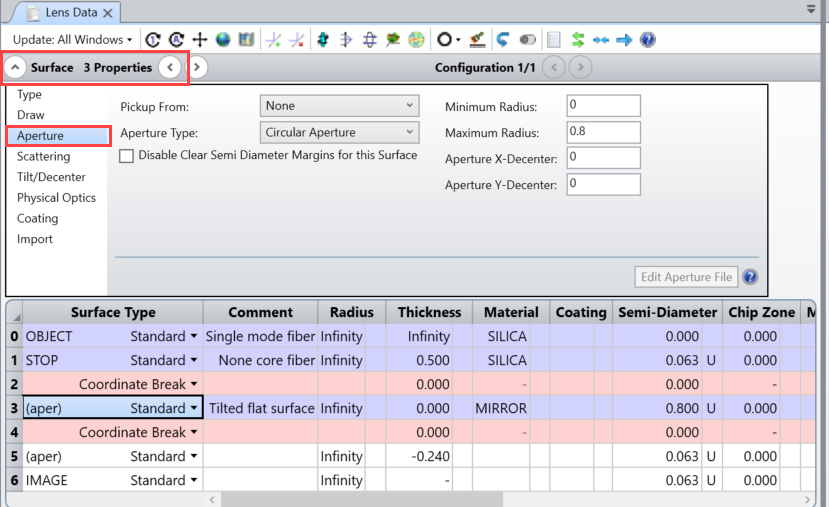
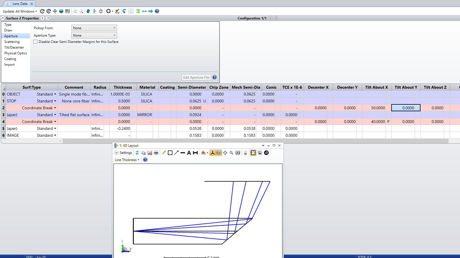
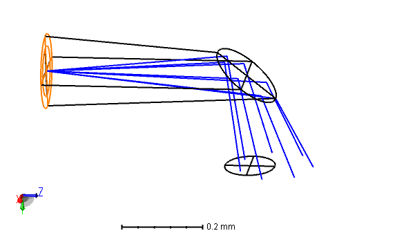
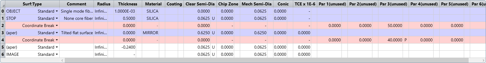
I would like to simulate that light travels through a single mode fiber, and a coreless fiber, and the end of the coreless fiber is a tilted flat surface, so the light will be reflected because of total internal reflection or reflective coating. My problem is that I can not keep the aperture constant (usually the cladding of SMF and my coreless fiber is 125um) because of the titled surface, as shown below. Is there any method that is able to keep the diameter consistent  (125um) ?  Thank you!


Oliver

Best answer by Alissa Wilczynski

Hi Oliver,

In your model, you’ve set fixed apertures on the front (row 1) and tilted (row 3) surfaces. The semi-diameters are measured relative to the surface’s local coordinate system, not a global coordinate system, so your aperture size on the tilted surface will need to account for the angle of tilt relative to the front surface and increase the semi-diameter accordingly. 

You’ll also find that just increasing the Semi-Diameter value on row 3 may not actually change your drawing. If you click somewhere in row 3 and then expand the surface 3 properties, you’ll be able to control the surface aperture with more granularity.


View original
Did this topic help you find an answer to your question?

Alissa Wilczynski
Zemax Staff
Forum|alt.badge.img+3

Hi Oliver,

In your model, you’ve set fixed apertures on the front (row 1) and tilted (row 3) surfaces. The semi-diameters are measured relative to the surface’s local coordinate system, not a global coordinate system, so your aperture size on the tilted surface will need to account for the angle of tilt relative to the front surface and increase the semi-diameter accordingly. 

You’ll also find that just increasing the Semi-Diameter value on row 3 may not actually change your drawing. If you click somewhere in row 3 and then expand the surface 3 properties, you’ll be able to control the surface aperture with more granularity.


  • Infrared
  • October 28, 2021
Alissa Wilczynski wrote:

Hi Oliver,

In your model, you’ve set fixed apertures on the front (row 1) and tilted (row 3) surfaces. The semi-diameters are measured relative to the surface’s local coordinate system, not a global coordinate system, so your aperture size on the tilted surface will need to account for the angle of tilt relative to the front surface and increase the semi-diameter accordingly. 

You’ll also find that just increasing the Semi-Diameter value on row 3 may not actually change your drawing. If you click somewhere in row 3 and then expand the surface 3 properties, you’ll be able to control the surface aperture with more granularity.


Dear Alissa, 

Thank you for answering. 

I understand what you mean. Just want to correct one typo in my lens data editor. The semi-diameter of Surface 3 should be 0.0625 instead of 0.625. 


Oliver


  • Infrared
  • October 28, 2021

I indeed find a method to keep the aperture constant (according to what I undersstand).

I can set the Aperture Type of Surface 3 as Elliptical Aperture, the X-Half Width is 0.0625 (just the radius of the fiber cladding), and the Y-Half Width is 0.0973. 

Here the Y-Half Width comes from: 0.0625/cos(50°)≈0.0973,  and the tilted angle is 50 degree.

However, I wonder if there is an automatic way to do this, for example, Pickup or ZPL Macro?

Thank you. 


Oliver


Reply


Cookie policy

We use cookies to enhance and personalize your experience. If you accept you agree to our full cookie policy. Learn more about our cookies.

 
Cookie settings