Solved

How to do wedge tolerance of a lens in Sequential lens design

  • 9 September 2023
  • 5 replies
  • 83 views

Badge

Hi all,

I try do a wedge tolerance analysis for sequential design with doublet lens. However, I couldn’t find the operands for it. Someone suggested me use TETX/TETY operands. However, the TETX/TETY is the tilt of the whole doublet group that pivoting its front surface vertex. Therefore, TETX/TETY tolerance operand is for alignment error. The wedge tolerance for doublets is more like doublet roll tolerance. Even though, both will cause optical deviation, I am not sure how correct to use TETX/TETY (alignment tolerance) for doublet roll tolerance. How you do wedge tolerance analysis? Any advices and thoughts are helpful.

Thanks,

Xiaolei

icon

Best answer by Jeff.Wilde 9 September 2023, 22:43

View original

5 replies

Userlevel 7
Badge +3

Use the surface tilt in Y to model wedge (you only need one surface per singlet) and then use TETZ to rotate the whole element randomly around 360 degrees. This won’t do anything for the sensitivity analysis as 0 = 360 degree rotation, but during Monte Carlo you will get every rotation angle represented.

  • Mark
Userlevel 7
Badge +3

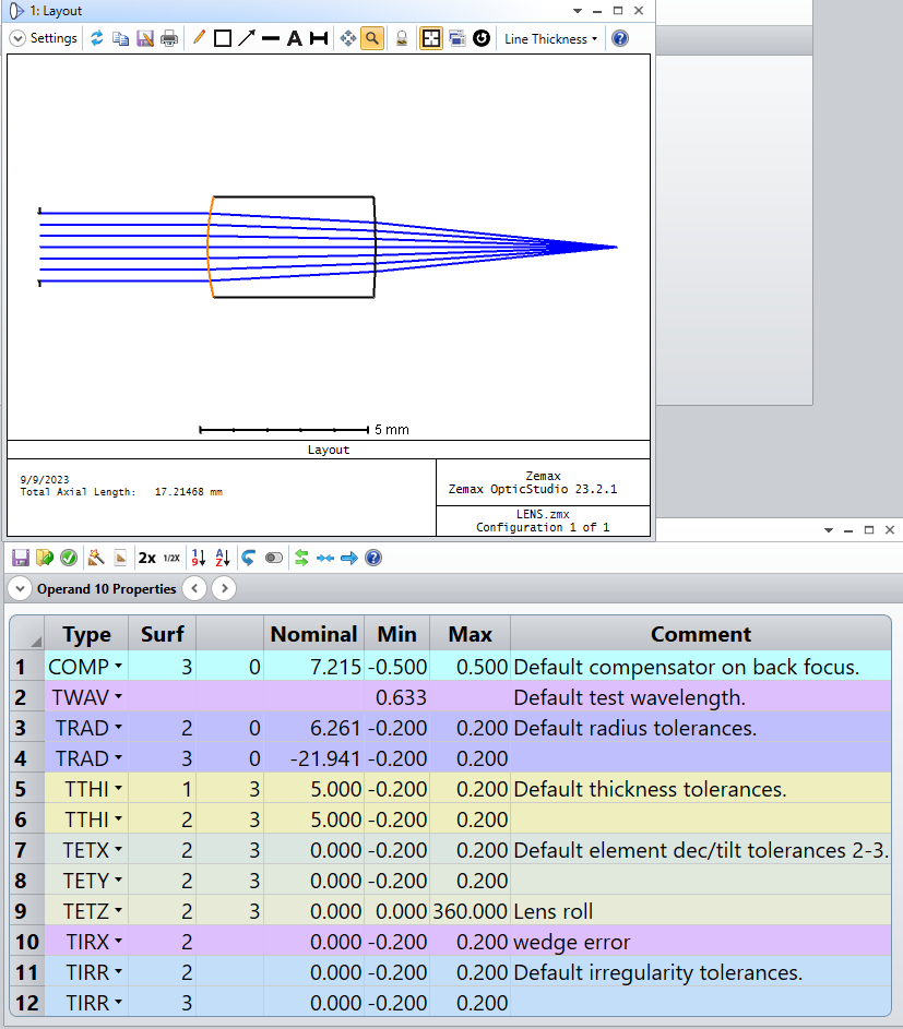
Here’s an example:

Surface 2 is wedged with respect to surface 3 by line 10 in the tolerance editor. Line 9 TETZ rolls the component formed by 2 and 3 to be anywhere between 0 and 360 degrees.

  • Mark
Userlevel 7
Badge +3

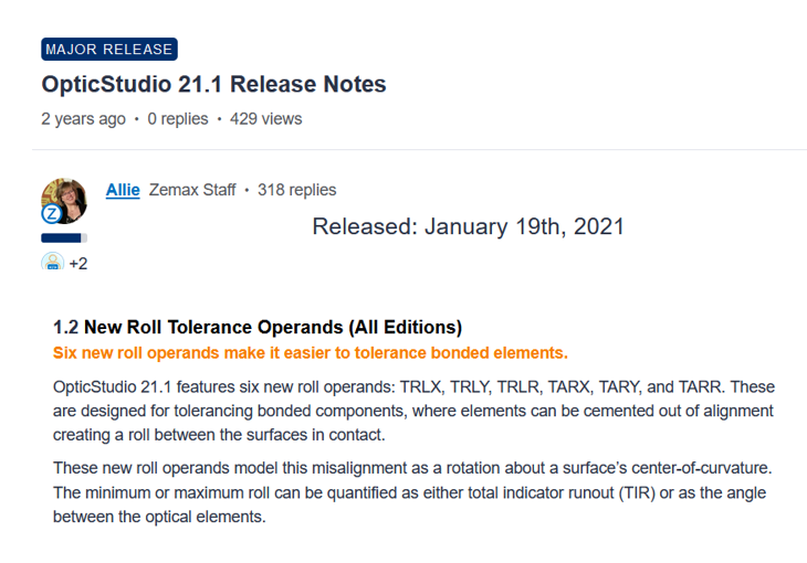
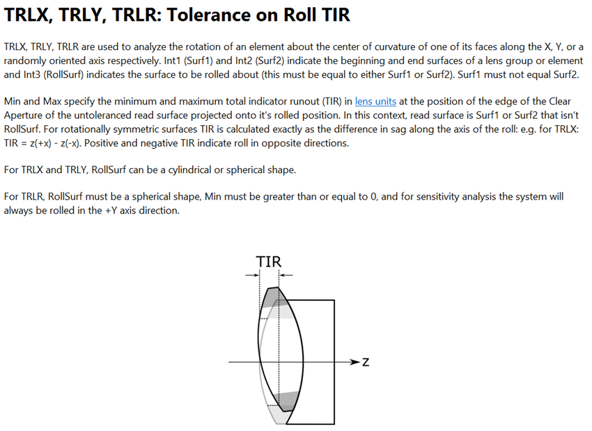
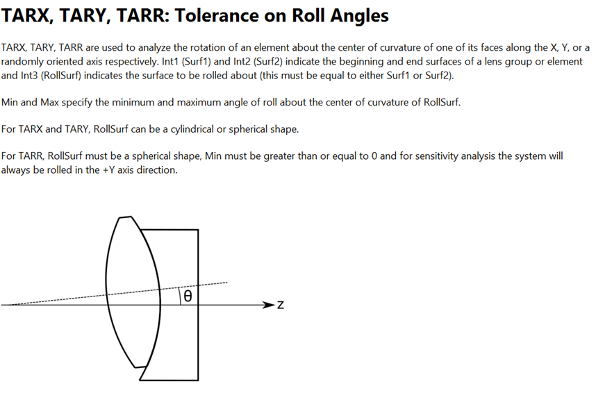
You may also want to look at the roll tolerance operands that were added in 2021:

which allows for quantifying the roll via TIR or angle.


Regards,

Jeff

Userlevel 7
Badge +3

That’s a good point Jeff, thanks.

Another thing just occurs to me. When we design a doublet, we can use a short cut that sequential ray tracing provides and model the doublet using only three surfaces. But when tolerancing, in other to get the kind of offset Jeff shows in his reply, it’s essential that you model the doublet as two separate singlets: in other words you need to use four surfaces to define the doublet, not three. Each singlet uses two independent surfaces.

Now during optimization, we can use only three surfaces because the rear of element 1 must have the same radius of curvature (etc) as the front surface of the second element. But for tolerancing the doublet, you must allow them to be different, so they can have slightly different curvatures as well as positions.

OpticStudio does this automatically for you when you export to CAD or convert to NSC, as these are true 3D solid models. But you have to do it yourself for tolerancing. There’s a long-standing feature request to add this capability to the Design Lockdown tool, but for now you have to do it yourself.   

Badge

Thank you, Jeff and Mark! They are very helpful. I figured it out based on your suggestions.

Best,

Xiaolei

Reply