Solved

How do vignetting factors affect my ray trace?

  • 23 May 2020
  • 7 replies
  • 751 views

Userlevel 6
Badge +2

When rays are clipped by apertures in my design, I can sometimes use 'Set Vignetting' to fix it. Why? How are the vignetting factors applying to the sysem?

icon

Best answer by Allie 23 May 2020, 00:42

View original

7 replies

Userlevel 6
Badge +2

We can think of vignetting factors as moving or compressing the entrance pupil while keeping the STOP stationary. I have provided a graphic below to show what I mean. In the graphic, you will see that in each image, the rays are launched from the same field point. The red rays represent the marginal rays, and the black rays represent the Chief Ray. The rays are being launched towards the pupil (gold) which is placed with respect to the STOP (black).


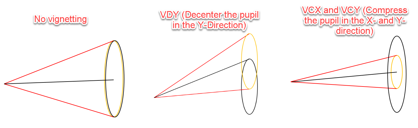
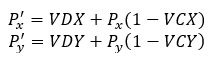
Above, we see that when no vignetting factors are applied, the entrance pupil is simply an image of the STOP surface, centered on the STOP surface. When we apply decentered vignetting, then the pupil is moved in the X or Y direction, but retains its size. When we apply compression vignetting (VCX or VCY) then the pupil remains at its original location, but the size is reduced. In all cases, the rays are launched so they fill the pupil.


We can use vignetting to update the size or direction of the bundle of rays a field sends into the system. Doing so will affect the location of rays, which may affect the output of some of the ray-tracing optimization operands. For example, let's say we are interested in the Y-direction landing coordinate of the +Y marginal ray. We can obtain this coordinate by using the operand REAY in the following way:


200522-153948-image.png


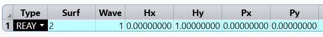
This operand will give us a different value for each of the three scenarios above. In all cases, we are tracing the ray at the +Y edge of the bundle, but it is landing at a different location depending on how the vignetting is applied. 


To get an idea of when vignetting factors should be applied, see the Knowledgebase article 'How to use vignetting factors.'


Userlevel 6
Badge +2

Vignetting factors can be utilized to help generate 2D plots of ray data. For example, using the fact that the Chief Ray changes location as decentered vignetting is applied, we can extract the angle of incidence data for all rays at the Image surface. Attached is an example file.


In this file, I am using decentered vignetting to move the pupil, thus moving the Chief Ray landing coordinate on the STOP surface. We can see in the image above that if I set VDY = 1, the pupil will be moved in such a way that the Chief Ray follows the original path of the +Y marginal ray. In other words, the Chief Ray will now have the same landing coordinates and incident angle as the marginal ray in the original, unvignetted setup. In this way, we can set the decentration of the pupil to be variable, and trace the Chief Ray alone to attain a plot of incident ray angles at the Image for all rays across the pupil.


In order to trace the Chief Ray angle of incidence for the plot, we use the RAID operand as the dependent variable. RAID accepts six inputs:


  • Surface at which the angle will be analyzed

  • Wavelength we are tracing

  • Hx, Hy (field normalization coordinates)

  • Px, Py (pupil normalization coordinates)


We have some documentation on the normalization coordinates in the Help System file “Conventions and Definitions > Normalized Field Coordinates” and “Conventions and Definitions > Normalized Pupil Coordinates”. If you aren’t familiar with the normalization coordinates, then take a look at those files.


To trace the Chief Ray of a field, we will choose Px = Py = 0. This is the ray that runs through the center of the pupil. As discussed above, this is the only ray we need to trace because the vignetting factors will move it to the correct positions across the pupil. The field coordinates define the starting field point for the ray. For the on-axis field, Hx = Hy = 0. For the maximum field point, Hy or Hx = 1. Because this file only has one field, I used Hx = Hy = 0 to trace the on-axis field coordinate. 


With these inputs, I have generated a 2D plot of angle of incidence data on the image surface:


Userlevel 6
Badge +2

Recently, a colleague shared a quick demo with me about vignetting factors. I am posting his explanation and attaching the demo he provided here:


I put together a quick demo about the Vignetting Factors in OpticStudio. This is a good way of visualizing the Px’ and Py’ equations as you change VDX, VDY, VCX, VDY, and TAN:


In the attached file, the Blue surface is the full Entrance Pupil without any vignetting factors while the Green surface is the vignetted Entrance Pupil; the Blue & Green rays are the +/- X & Y marginal rays.


You can ignore the Lens Data Editor & Multi-Config Editor as these are only there to setup dummy surfaces with 2 configurations (one with the vignetting factors and one without). When playing around with the vignetting factors in the Field Data Editor, just make sure that you’re always on Configuration 2.

Dear Allie,


How the vignetting angle can be found?


Reponse will be appreciable.


Regards,


Faheem Ahmad

I am using the ZPL to find the Vignetting factor. So how to find the vignetting angle using ZPL for a fixed lens system?


Can you please help?


-Faheem Ahmad

Userlevel 5
Badge +2

Hello Faheem,


Thanks for your question here!


You can use the following numeric macro functions to get field and vignetting information:


You may find more info in the Help file under:

The Programming Tab > About the ZPL > Numeric Functions


Best,


Csilla

Thanks Scilla I got it.


Thank you for your kind appreciable response.


Regards,


Faheem

Reply