Hi Tali,
Thanks for getting back to us!
The hologram deviates ray paths according to the following equation:
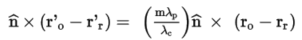
This equation above doesn't consider the index of the materials at two sides of the hologram surface. If one of the rays is from different material, then we should multiply its unit vector by the index where the ray is in. For example, if the hologram is attached on a glass with index of n_g and is used in reflection, then we should write incident readout beam and the refracted beam as n_g*r'_r and n_g*r'_o. This is already handled by OpticStudio.
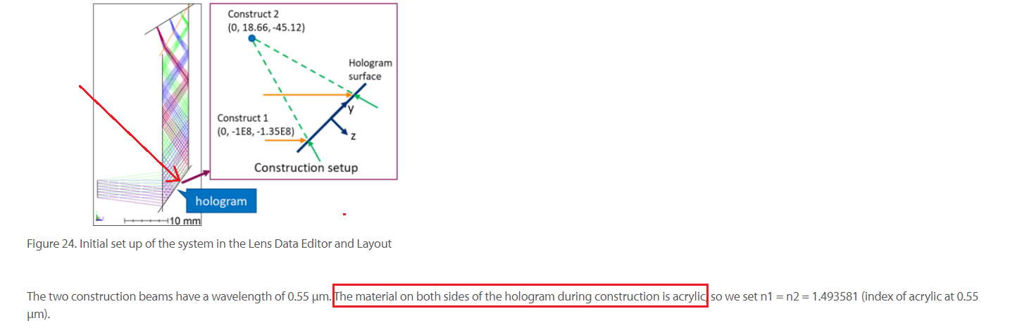
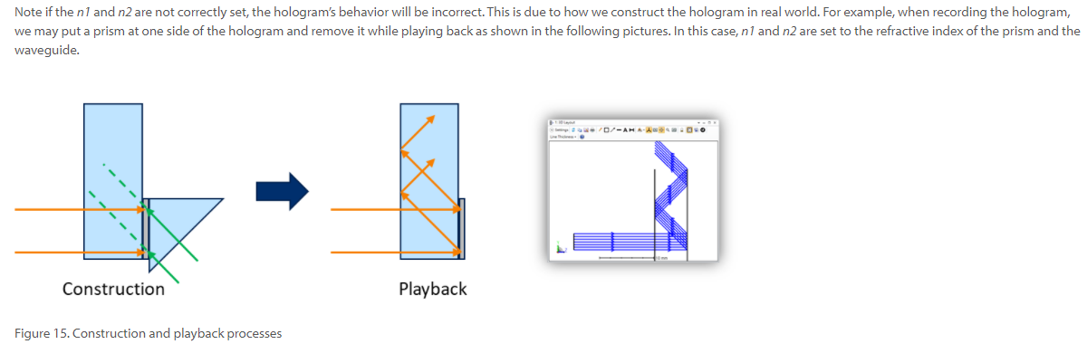
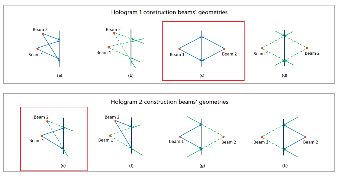
However, the construction beams are always assumed to be in the AIR, as you mentioned. There is no parameter for defining the index of the material where the construction beams are. In cases where the hologram is optically manufactured in a non-AIR material, the construction wavelength should be effectively changed from λ_c to λ_c/n_g.
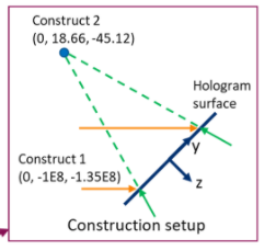
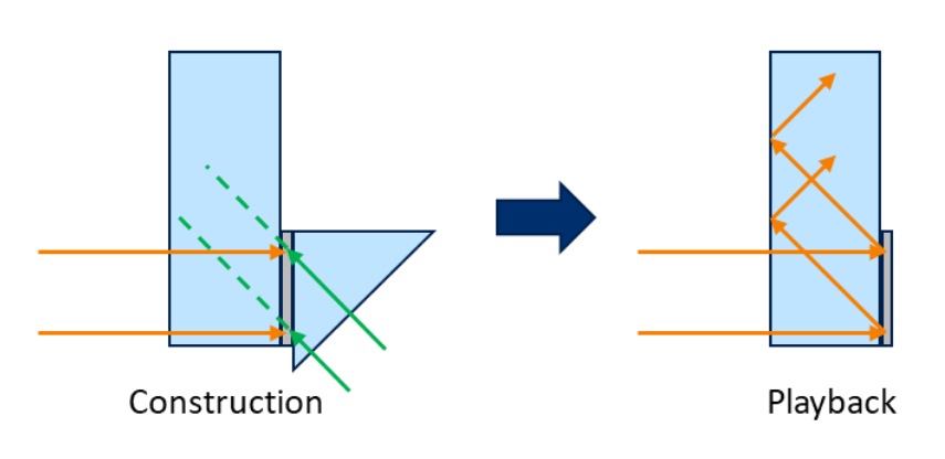
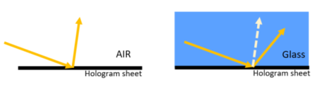
Please note that, when the index of the materials at two sides of the hologram are different, we should expect rays to be diffracted to different directions. This is exactly what we would expect for a grating diffraction. Shown below is a sketch that depicts this concept.
Please also note that to use a hologram in reflection, its Material must be set to “MIRROR”. This explicitly indicates OpticStudio that rays propagate in the opposite direction after hitting the hologram surface.
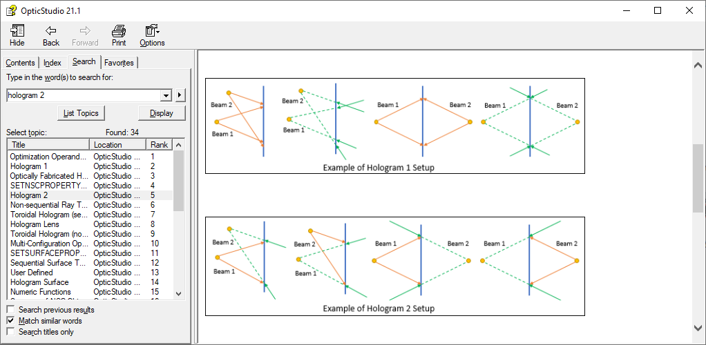
You may find more information about this in the Help at:
The Setup Tab > Editors Group (Setup Tab) > Lens Data Editor > Sequential Surfaces (lens data editor) > Hologram 1 and Hologram 2
and in this knowledgebase article:
How to model holograms in OpticStudio · MyZemax
I hope this helps, but if you have further questions, please ask!
Best,
Csilla