

I’m using Non-Sequential mode to model some interference behavior.
I’m trying to figure out if the Phase that is reported by “Coherent Phase” from a detector rectangle INCLUDES the phase shift that occurs at boundary reflections (from Fresnel equations), or if that phase is purely based on the OPL along a ray?
I spent the whole morning reading KB articles and documentation on this and eventually I had some luck seeing the expected pi phase shift by using a polarized ray source (Jx=1) and detector rectangle with Polarization parameter = 1. However, Jy=1 and detector Pol = 2 did NOT show a phase shift even though my ray is incident at near normal incidence. I saw no impact of changing the Polarization Conversion method (X-axis vs Y-axis) used. Very confusing.
What I want is interference fringes that show the proper phase including the effect of the phase shift induced by Fresnel coefficients that works for both polarization orientations. Is there a way to reliably get to this point? Thanks for any guidance you can provide.
-Craig
P.S. Documentation Error?
As part of this study of polarization behavior I stumbled onto 'Ideal' coatings. Under the simple 'Ideal' coating (p1857) I see a description that looks correct:
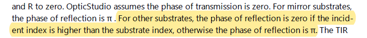
However, under 'Ideal2' coating on the next page, it looks like the described behavior is the opposite:
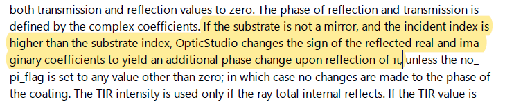
Actually, it seems like the Ideal2 coating phase should be totally determined by the coefficients provided by the user, so it's confusing that this text shows up here at all. Then on top of that the behavior seems backwards.
Irregardless of these promising descriptions, I had no luck seeing any change in phase behavior with these two coating types.
-C