Solved

Focusing and Collimating light sources in NSC with merit functions

  • 21 April 2021
  • 3 replies
  • 2620 views

Hi there,


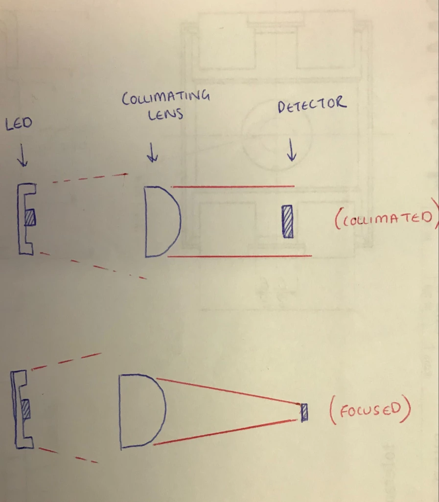
I just have some queries about using merit functions to determine the z-distances between the components within my light path, to create both a focused and a collimated light path (see image 2 below).


Overview of the light path design:


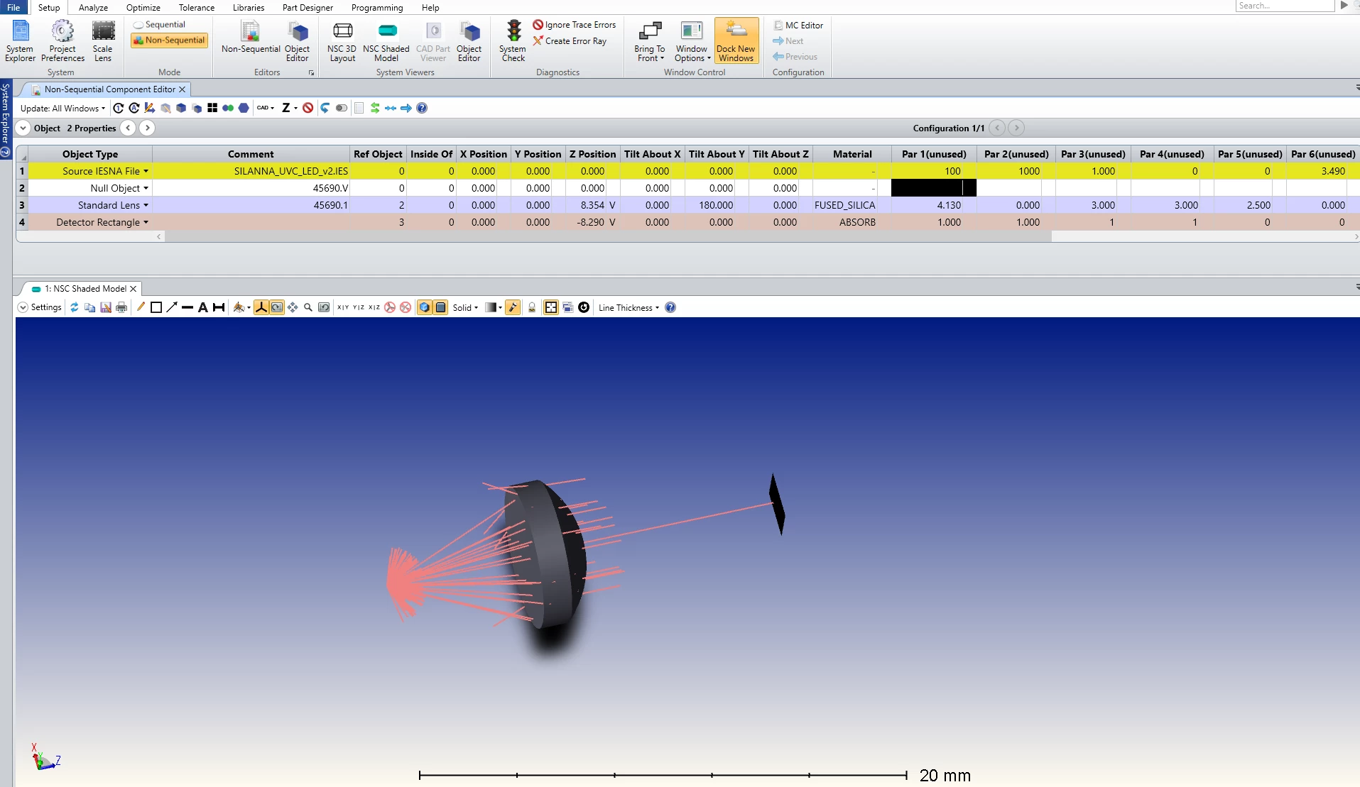
At the moment I have a stripped back version of my final light path (see image 1 below). It includes a UV LED operating at a wavelength of 0.233, an Edmund Optics lens (imported from the 'Lens Catalogue'), and a detector rectangle. My objective is to use the merit function to determine the z-distances between each of these components to generate a collimated light path and a focused light path. A photodiode has not yet been chosen so I currently need to know where to place my components for a collimated path (larger diode) or a focused path (much smaller diode). At the same time, I want to be able to get the most power possible at the detector.


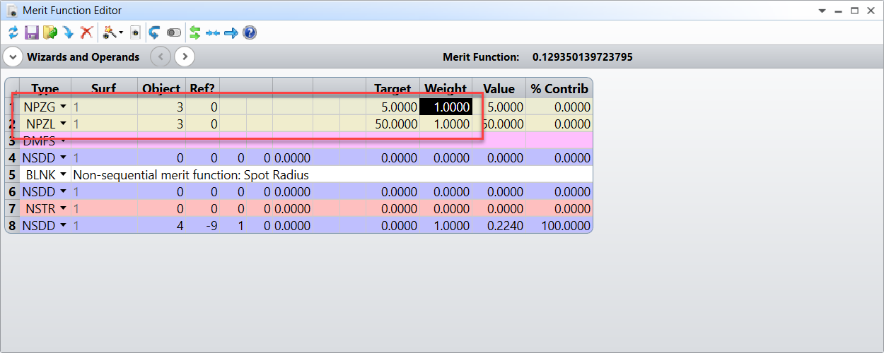
I was just hoping to gain some advice and insight into the best method / approach to detemine these z-distances. I have been playing around with the optimization wizard and the use of the criteria settings. In particular, the RMS Angular Radius based upon previous forum posts. But would like some expert advice on how to go about it.


Thank you.

icon

Best answer by Berta.Bernad 21 April 2021, 10:50

View original

3 replies

Userlevel 3
Badge +2

Hi Jonathan,


Thanks for your post here!

If you want to optimize beam to be collimated, as you said, you can use the Optimization Wizard in NSC and choose RMS Angular Radius as criterion to be 0. Additionally, a 'Minimum Flux' target can be specified. This is sometimes necessary to avoid solutions with no rays landing on the detector. 

In terms of determining the best focus location for your system, you can also use the Optimization Wizard to build a Merit Function to analyze the RMS Spot Radius.

It can be also a good idea to add some constrains (such as maximum/minimum distances) to avoid non-physical solutions. 

The Optimize Tab (sequential ui mode) > Automatic Optimization Group > Merit Function Editor (automatic optimization group) > Optimization Operands by Category > Constraints on Non-sequential Object Data

You may find useful these articles that explains how to perform a Non-Sequential Optimization:


Using the OpticStudio Non-Sequential Optimization Wizards

How to optimize non-sequential optical systems


And some more information on Optimization can be found in the Help Files at “The Optimize Tab (sequential ui mode) > Optimization Overview”.

Best,

Berta

Hi Berta,


I understand how to set constraints on Total flux in the merit function, but how do you suggest I set constraints on Z distances to avoid non-physical solutions?


Thanks.


Userlevel 3
Badge +2

Hi Jonathan,


If you navigate to that section in the Help System file The Optimize Tab (sequential ui mode) > Automatic Optimization Group > Merit Function Editor (automatic optimization group) > Optimization Operands by Category > Constraints on Non-sequential Object Data you will see that there are several operands for constraints on non-sequential object data. 


To set constrains on Z distances, you can use these:


NPZV will allow you to target a specific Z location, but you can also set a range of distances (to avoid placing the object too close or too far) with NPZG or NPZL.


So if I want to place object 3 somewhere between 5 and 50 mm, I'd add something like this in the Merit Function Editor:


Keep in mind that theses user added operands should be placed before the DMFS operand (if you are using the Optimization Wizards).


Best,


Berta


Reply