I'm trying to understand how to correctly set up an extended source. I want to image a 5 um fiber core through a spectrometer. The Help file indicates that the IMA size in the Partially Coherent Image Analysis (File Size) is different than in the Geometric Image Analysis (Field Size).
The help file says that the "File Size" is "The full width in lens units of the region defined by the file measured in image space." In contrast to the "Field Size," which is defined as "This value defines the full width of the square image file in field coordinates, which may be either lens units or degrees."
This would indicate that "File Size" is the width in the image plane, while the "Field size" is the width at the object plane. If my system as a magnification of two, then I need to set the "File Size" = 10 um and the "Field size" = 5 um. Is this correct? Is there a way to automatically account for magnification while using the Partially Coherent Image Analysis tool, or do I have to manged it manually? Perhaps take the output from the Paraxial Gaussian Beam data?
Thanks,
Andrew

Solved
File Size verse Field Size
Best answer by Mark.Nicholson
Hey Andrew,
This can be confusing, because the size of the file is defined differently in Partially Coherent Image Analysis than it is for the other bitmap based features. That's because we expect you to want to look at image quality at the scale of the PSF or maybe 10xPSF, so that you can see the effects of partial coherence as the image enters diffraction-limited performance. So, we wanted to make it easy to work in image-space rather than object space as per the other bitmap features.
In the double Gauss 28 degree sample file, I set up the PCIA like so:
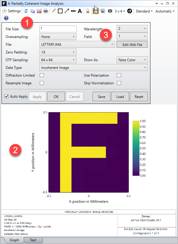
In this case we use the letterF.IMA file which is a 7x7 bitmap. With no oversampling or zero padding (as done here) you can see that you get exactly what was stated: (1) a file size of 1 gives (2) an image of the letter F which is exactly 1 mm across, or +/-0.5 mm. This is 'The full width in lens units of the region defined by the file measured in image space', as stated.
Now note setting (3), the Field setting. This is where the IMA file is centered, in this case it is centered on field point 1 which is the center of the field of view in this case. If you select field point 2, you will be an image of size 1mm centered on that field.
So to calculate the real size in object space, you'll need to account for both the magnification and distortion of the lens by tracing real rays that land at the top and bottom of the image and getting their coordinates on the object surface. However, the image is likely very small so that you can see the effects of the spatial coherence function, and so distortion is unlikely to be an issue. It's best to remember that we expect the image size to be small, or the order of 10*PSF or so when using this feature.
View originalThis can be confusing, because the size of the file is defined differently in Partially Coherent Image Analysis than it is for the other bitmap based features. That's because we expect you to want to look at image quality at the scale of the PSF or maybe 10xPSF, so that you can see the effects of partial coherence as the image enters diffraction-limited performance. So, we wanted to make it easy to work in image-space rather than object space as per the other bitmap features.
In the double Gauss 28 degree sample file, I set up the PCIA like so:
In this case we use the letterF.IMA file which is a 7x7 bitmap. With no oversampling or zero padding (as done here) you can see that you get exactly what was stated: (1) a file size of 1 gives (2) an image of the letter F which is exactly 1 mm across, or +/-0.5 mm. This is 'The full width in lens units of the region defined by the file measured in image space', as stated.
Now note setting (3), the Field setting. This is where the IMA file is centered, in this case it is centered on field point 1 which is the center of the field of view in this case. If you select field point 2, you will be an image of size 1mm centered on that field.
So to calculate the real size in object space, you'll need to account for both the magnification and distortion of the lens by tracing real rays that land at the top and bottom of the image and getting their coordinates on the object surface. However, the image is likely very small so that you can see the effects of the spatial coherence function, and so distortion is unlikely to be an issue. It's best to remember that we expect the image size to be small, or the order of 10*PSF or so when using this feature.


Reply
Enter your E-mail address. We'll send you an e-mail with instructions to reset your password.
Need more help?
To Chinese users:
Do not provide any information or data that is restricted by applicable law, including by the People’s Republic of China’s Cybersecurity and Data Security Laws ( e.g., Important Data, National Core Data, etc.).
不要提供任何受适用法律,包括中华人民共和国的网络安全和数据安全法限制的信息或数据(如重要数据、国家核心数据等)。