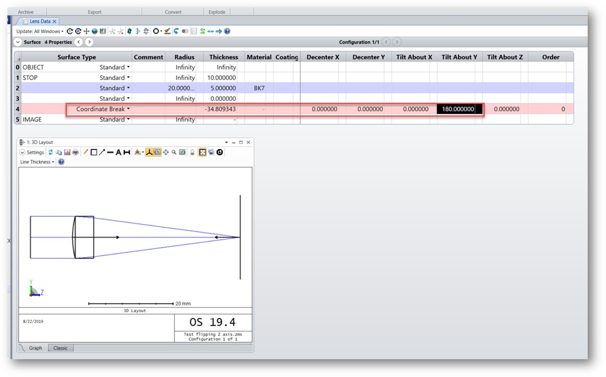
FEA, SigFit & ZEMAX: coordinate system orientation
Hi,
The standard method for defining the direction of the Z-axis is that positive is towards the image plane. This is opposite to what my team's FEA & CAD team has been doing and prefers. We are looking at integrating SigFit for thermo-optical analysis.
For implementation of SigFit the coordinate systems need to align.
Does anyone have any experience in changing the Z-axis orientation? The CAD & FEA team prefers that we first investigate just changing the definition of positive Z in ZEMAX. Or will it be a better procedure for the FEA & CAD to default to the ZEMAX optical system Z-orientation (positive towards the image plane)?
Regards,
Dalene
Enter your E-mail address. We'll send you an e-mail with instructions to reset your password.


