Solved
Error: Not Enough Intersections Allocated to Finish Ray Trace
I am trying to simulate a reflector that I put over 12 LEDs. To kind of collimate the light.
I import a STEP file, setup locations for 12 LEDs, set analyze rays to 1E6, raise the number of intersections for non-sequential mode to maximum which seems to be 4000 but when I run tracing, at 0.00% it says error...
Anyway I can get past this?
Also, am I using the coating correctly on the reflector? I set the Coating to I.95, does that mean each reflected ray will loose 5% power or 5% of rays will not reflect?
Project attached, you can download the Source File from here: http://mktg.ledengin.com/files/products/optical/LZ4-00Rx08-5m.dat
Best answer by Thomas Magnac
Hi Andrey and David,
I just had a look at your file, and I believe I know what is causing the issue.
David is right, I.95 means 95% transmission and 5% reflection.
<<A common cause of too many intersection is the many internal Fresnel reflections inside a glass volume. This can be eliminated by setting a minimum ray intensity in the non-sequential section of the system explorer. For example, setting the "minimum relative ray intensity" to 0.01 means that any segment that falls below 1% of the initial ray intensity will not be traced. You should set this value to be high enough to still trace all the important energy, but low enough to prevent tracing rays that do not significantly contribute to the result. When you trace rays, the ray trace dialog will report the total energy lost as 'lost energy (thresholds)'.>>
However, from the archive file, I can see that the checkbox ''polarization'' is unchecked.
This means that the polarization is not taken into account, therefore, a ray keeps its intensity without any losses.
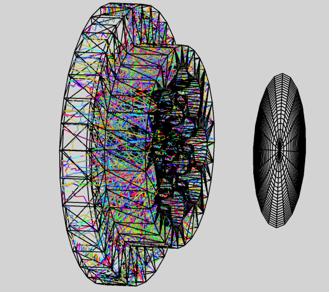
When a ray enters the CAD, it is traped in it and reaches the maximum allocated number of intersection:

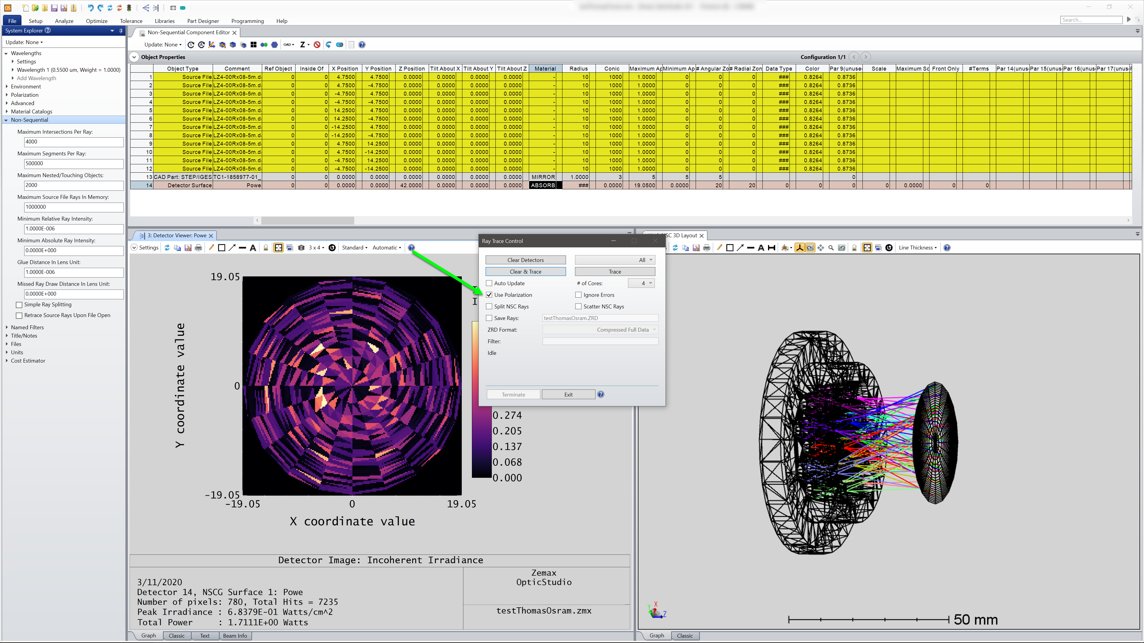
All I did to solve the problem is to turn polarization on by checking the box in the settings of the raytrace:

Now, the losses are taken into account, and the ray is terminated when it reaches the maximum number of intersection or the minimum intensity.
All the best,
-Thomas
PS: the rayfile is here: https://www.osram.us/ledengin/products/luxigen/lz4.jsp
I just had a look at your file, and I believe I know what is causing the issue.
David is right, I.95 means 95% transmission and 5% reflection.
<<A common cause of too many intersection is the many internal Fresnel reflections inside a glass volume. This can be eliminated by setting a minimum ray intensity in the non-sequential section of the system explorer. For example, setting the "minimum relative ray intensity" to 0.01 means that any segment that falls below 1% of the initial ray intensity will not be traced. You should set this value to be high enough to still trace all the important energy, but low enough to prevent tracing rays that do not significantly contribute to the result. When you trace rays, the ray trace dialog will report the total energy lost as 'lost energy (thresholds)'.>>
However, from the archive file, I can see that the checkbox ''polarization'' is unchecked.
This means that the polarization is not taken into account, therefore, a ray keeps its intensity without any losses.
When a ray enters the CAD, it is traped in it and reaches the maximum allocated number of intersection:

All I did to solve the problem is to turn polarization on by checking the box in the settings of the raytrace:

Now, the losses are taken into account, and the ray is terminated when it reaches the maximum number of intersection or the minimum intensity.
All the best,
-Thomas
PS: the rayfile is here: https://www.osram.us/ledengin/products/luxigen/lz4.jsp
Enter your E-mail address. We'll send you an e-mail with instructions to reset your password.


