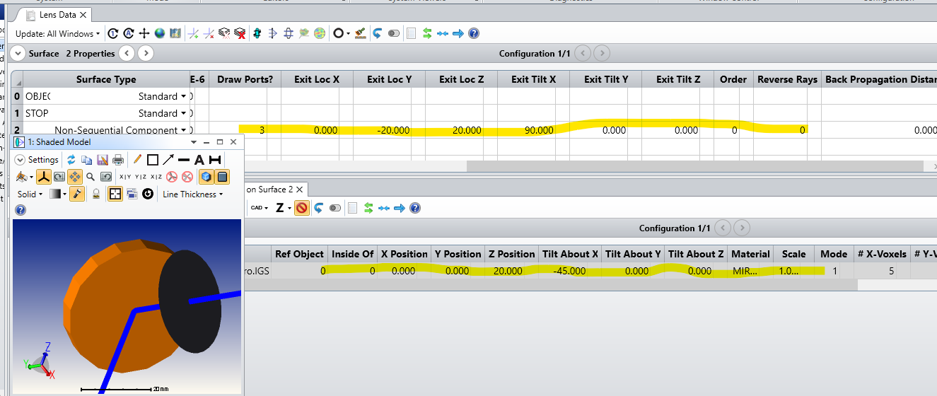
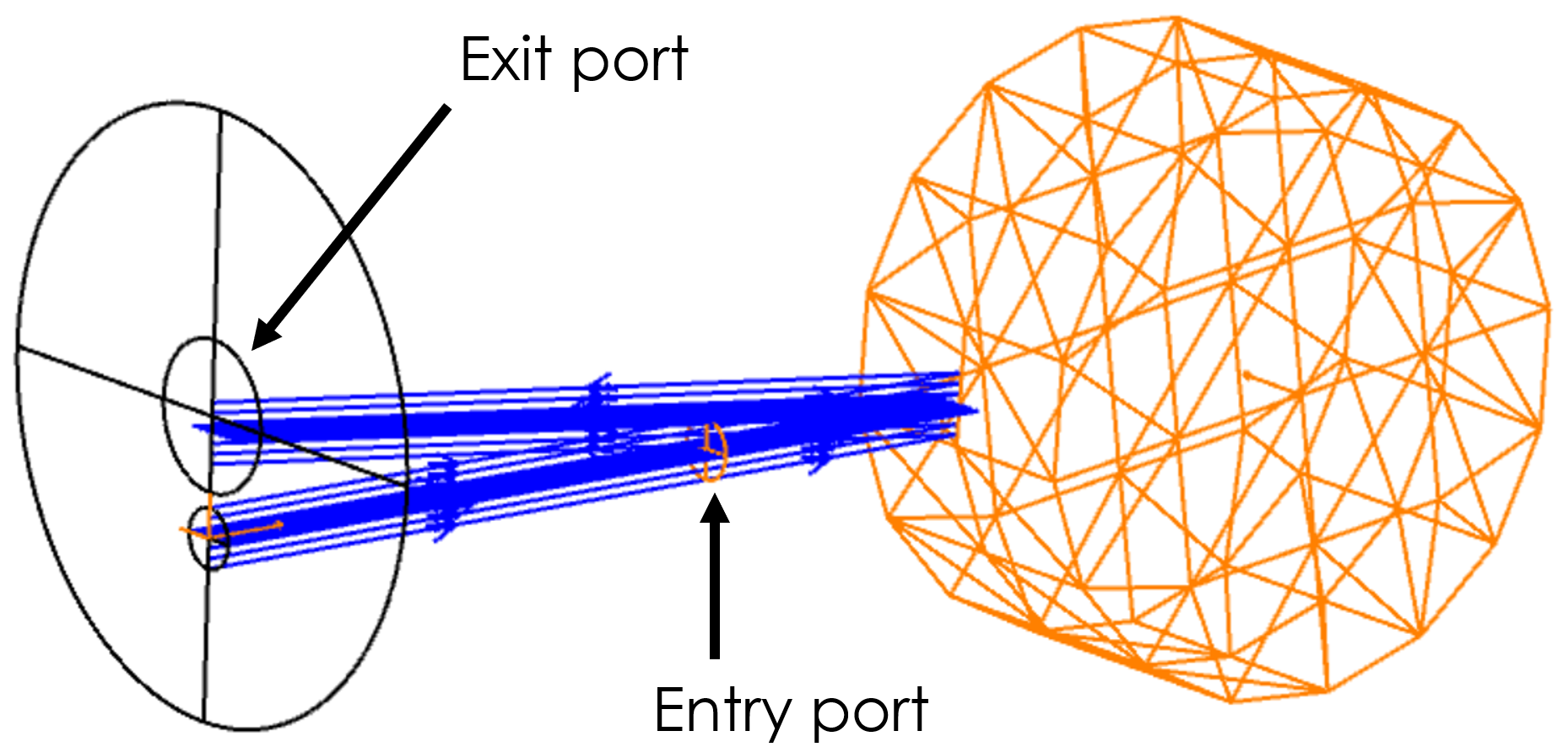
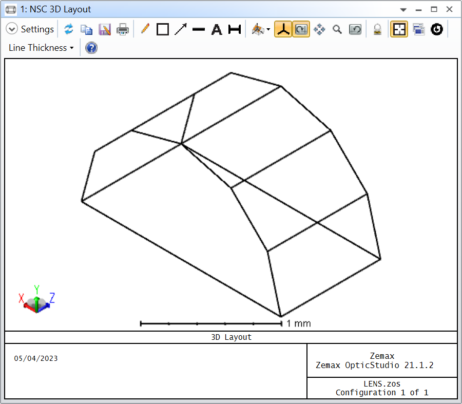
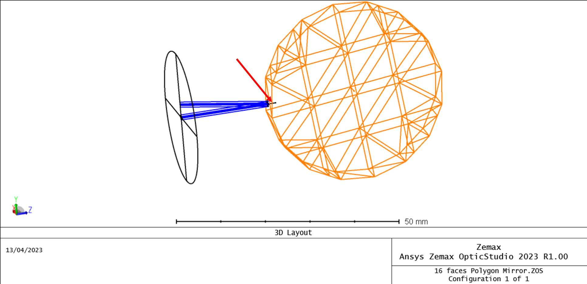
Could you advise me on how to set the entry/exit port and tilt parameters so my polygon mirror scan/reflect beam uses its face, instead of its main surface ( like on the drawing below)? I was playing with parameters (highlighted in yellow) and felt that I am going nowhere.
Thank you.
Regards,
Marzanna
Best answer by David.Nguyen
Hi Marzanna,
Are you using two different version of OpticStudio? The Zemax Part Designer is only available in the Premium edition, but I assumed you had it since you sent me a screenshot of it. I think what is happening is that someone has generated the polygon with a Premium edition and converted it to *.IGS so you could use it in your Professional. Anyway, I think you’ve found the workaround yourself.
About the Entry/Exit port, have you looked at this article? The Help File (F1) also has detailed information in the section: The Setup Tab > Editors Group (Setup Tab) > Non-sequential Component Editor > Non-sequential Overview > NSC ray tracing in mixed mode (with entry and exit ports).
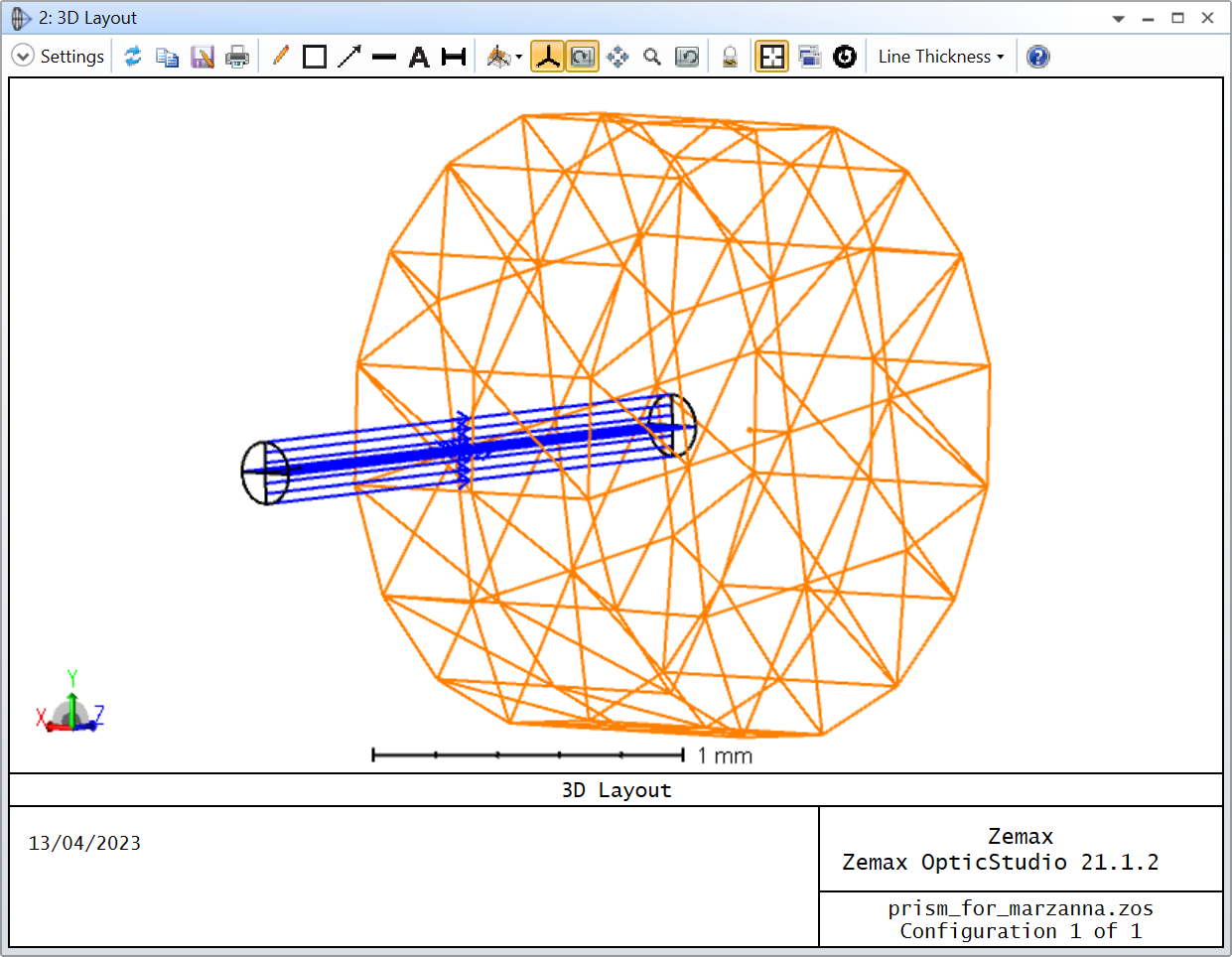
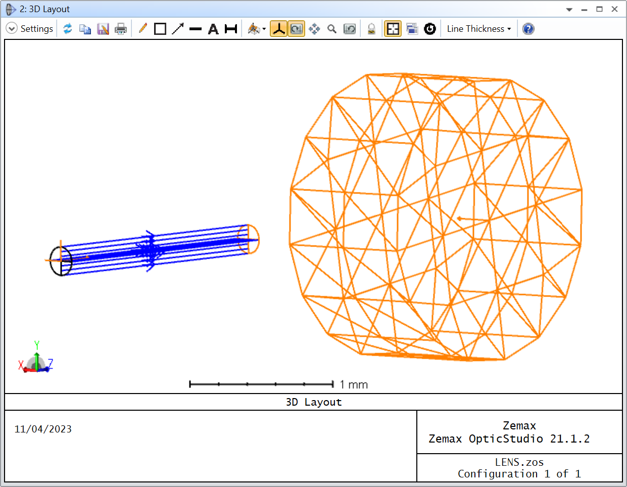
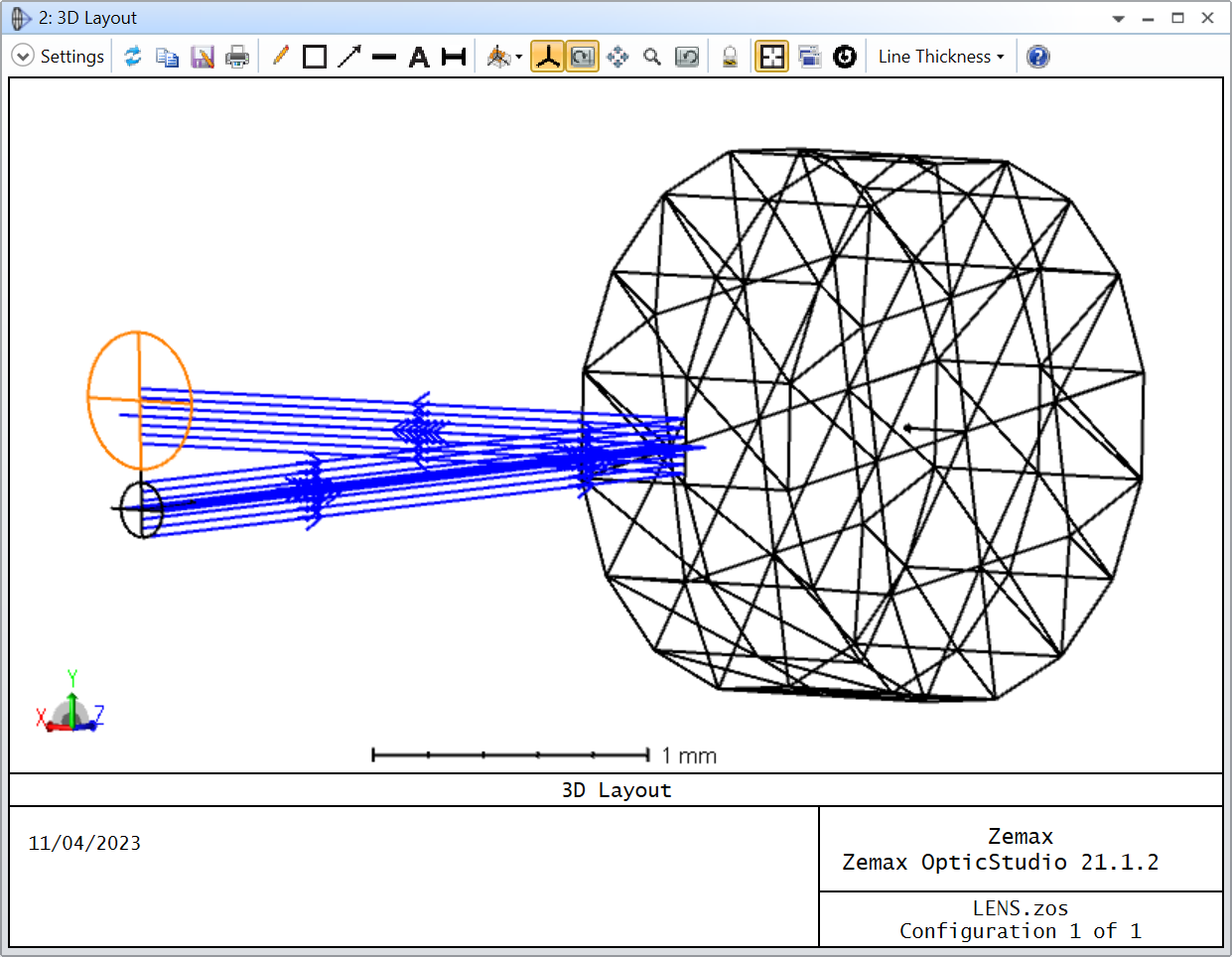
The Entry port is the aperture through which sequential rays are allowed to enter the Non-Sequential Component, and is defined by the Non-Sequential Component Surface itself. That is why we added a Z Position to the polygon. Without a Z Position = 2.0 on the polygon, this is what the 3D Layout looks like:
As you can see, the entry port is inside the polygon and the rays ignore the first surface of the polygon. This is because eventhough the polygon appears to intersect the rays before, those rays only enter (and therefore see) the Non-Sequential Component from the Entry port. If we wre to propagate those rays, they would reflect from the surface of the polygon after entering through the Entry port and stay trapped within the polygon:
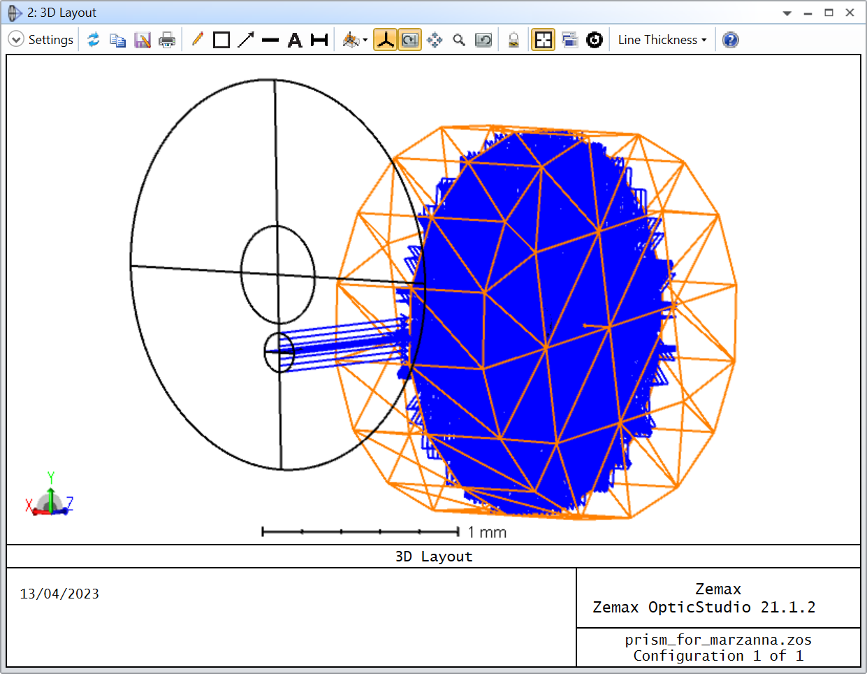
Similarly, the Exit port is the only place where rays are allowed to exit the Non-Sequential Component and continue in the rest of your Sequential system. If no ray makes it to the exit port, then you won’t see them propagate through the rest of your system.
The issue with your system is that the incoming rays overlap with the ones that are reflected by the polygon, and you don’t want the Exit port to overlap with the Entry port (otherwise the rays enter and exit the Non-Sequential Component right away), which is why I had to move the Exit port to a different location:
The arrow you are refering to is a local axis of a surface or object. People often use it to orient their surfaces and objects correctly. If you double-click on a surface in the Lens Data Editor and go to the Draw tab, there’s a checkbox called Draw Local Axis. You can toggle this checkbox and see what it does. Basically, it shows a local axis referenced to the corresponding surface (you can do the same with objects).
Why do you think your file isn’t right?
Its only my opinion, but in my modest experience, it is rarely a good idea to mix simulation and rendering. If I have to make a visual rendering, whether it be for a presentation or a figure in a paper, I’d do it outside OpticStudio. The ray angles don’t need to be exact if you just want to showcase your model. Also, OpticStudio is not the best tool to produce good visual rendering. If anything the color options are quite limited. And on the flip side, a simulation might turn out to be computationally intensive, and you want it to be as light as possible. The more complex a simulation becomes, the harder it is to also interpret the results. Therefore, for a simulation, I’d always try to have a simple a model as possible, and complexify it if the need arise. Again, this is just my opinion, and I’m always happy to help anyway if you want to continue down that route.
I can barely see in your screenshot that your polygon mirror is from a CAD file with a *.IGS extension. The first step when you work with CAD files is to figure out where the origin is within the CAD file. I’ve written about this in the case of CAD assembly, but it applies to CAD parts as well:
If you don’t know where the origin in that part is, then it might be tricky to position by trial and error, like you tried. But if you know where the part stands with respect to the origin, then know that OpticStudio will conveniently use the same origin as well, and it should be easier to locate.
If you share that file with us, we could try to figure out where the origin is and see how to position it according to your needs.
On that note, is a CAD object the only way to make such a prism? I feel like its an overkill and might add some overhead when you’ll be doing raytracing. There’s a user-defined object called “HalfCylinder” that comes with the OpticStudio installation file:
That could be another option: either make a user-defined object or use two “HalfCylinder”. I’ll think about it.
Thank you for helping me. I was advised by Zemax technical support that this will be the best way to build a polygon mirror. Sorry for not putting forward important information about this simulation - I had no idea that they are needed in order to find a solution. I am attaching the file. I would like to incorporate this polygon mirror into the sequential simulation, and it should work like scanning mirrors. That is why, it will be only a reflecting beam and I don’t need to specify the entry port.
I have started reading your answer on rotating an object, and my polygon mirror wasn’t made in external software but in Optical Studio ( I don’t know if that is matter)
If you’ve created that object with the Part Designer, then it is likely that the origin is the centre of one of the two polygonal faces.
I will try to answer your question as it is, but I’m still not convinced as to why you need a non-sequential CAD for this application. On that same note, have you had a look at this article?
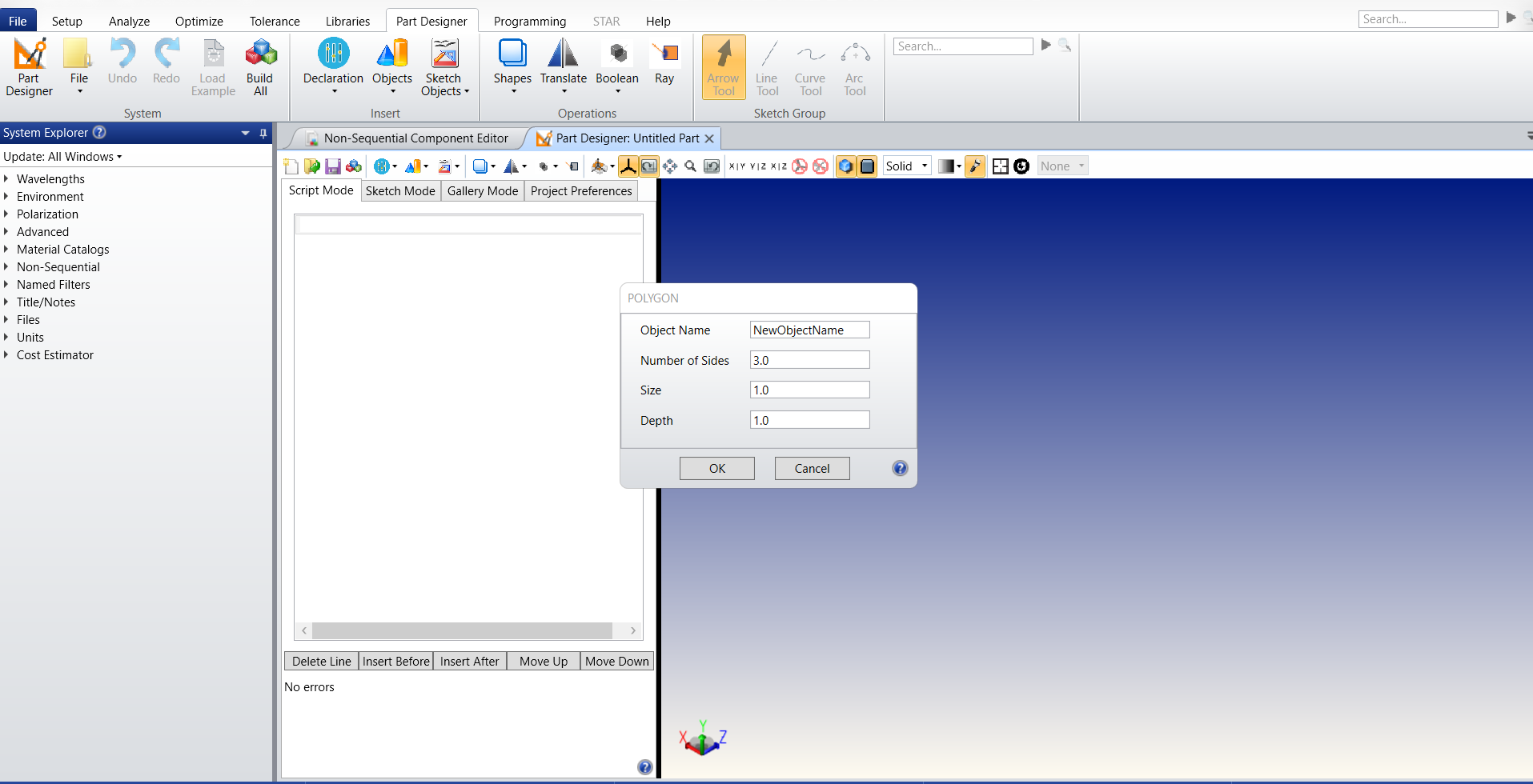
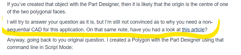
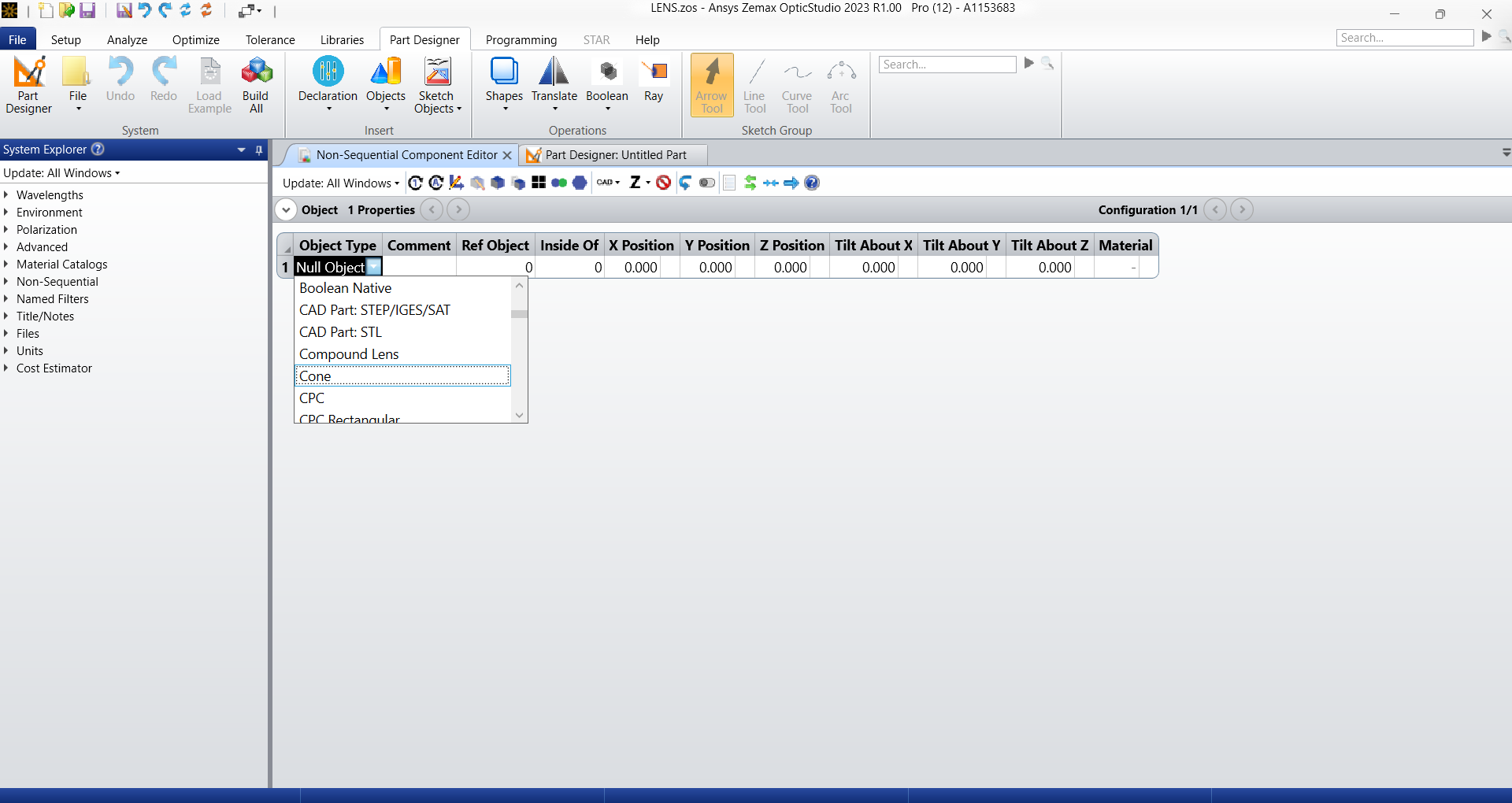
Anyway, going back to you original question. I created a Polygon with the Part Designer using that command line in Script Mode:
POLYGON NewObjectName, 16, 1.0, 1.0
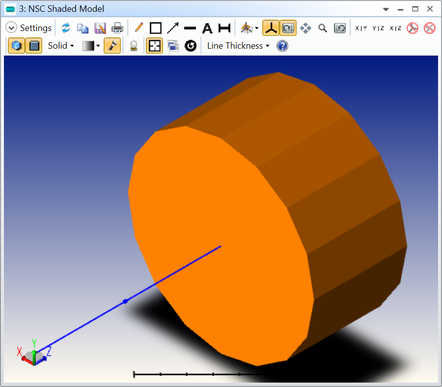
I save the object as *.ZPO and inserted it in the Non-Sequential Component Editor using a CAD Part: Zemax Part Designer object. I then mapped all the side faces to a single face (using the CAD tab of the Object settings) and made it reflective. To help visualize the situation, I added a Source Ray with a Z Position = -2.0:
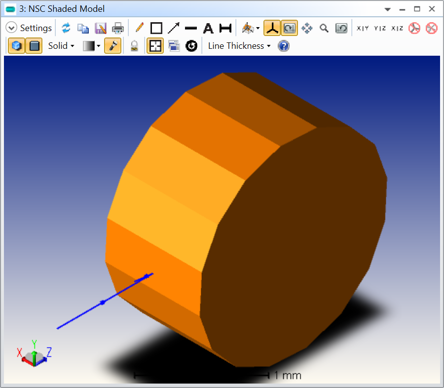
As you can see, the ray is striking the wrong surface. To solve the problem, I applied a Tilt About Y of 90 degree and a X Position of -0.5. I also applied a Tilt About X of 5 degree because otherwise the ray was striking an edge on the side:
Now, here’s the tricky part. The entrance port in mixed-mode will coincide with the local axis of the polygon, which is at the centre of one of its two polygonal faces. Therefore, your entrance port will be in the X-Y plane that slices this prism into two equal parts, meaning that the rays from the sequential source will be seen as appearing from inside the prism, if that makes sense. To circumvent this problem, I used a Z Position of 2.0 so that the entrance port is well clear of the polygon.
In mixed-mode, you have the column Draw Ports? that helps visualizing the Entrance and Exit ports:
In my example, the small orange circle where the rays stop is the Entrance port. Then the problem is the Exit port. Because your rays are reflected from the prism, I had to reposition the Exit port using a Exit Loc Y = 0.4, and Exit Loc Z = -2.0:
The main issue is that you don’t want the Exit port (larger orange surface where the rays terminate in my screenshot above) to overlap with the Entrance port otherwise, the rays in the overlaping regions will simply not see the CAD object.
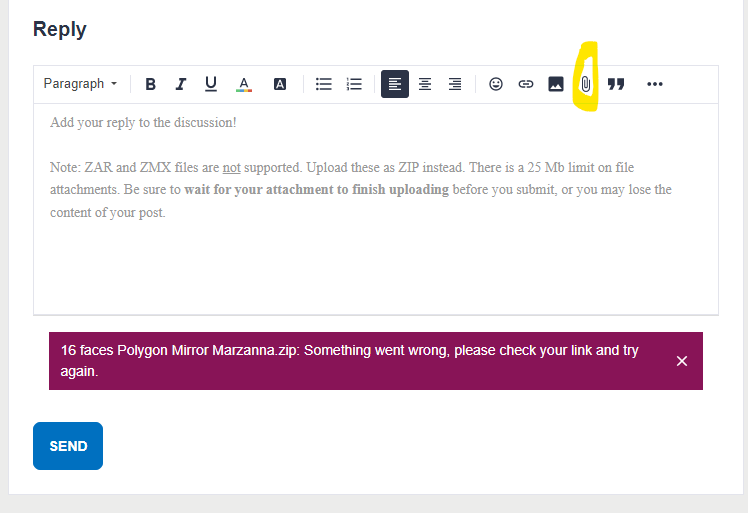
I’m attaching my example to this reply for your reference. If you want to share a CAD object, simply create an archive (File..Create Archive) of your file (the CAD will be embedded in the archive), zip it, and upload it here.
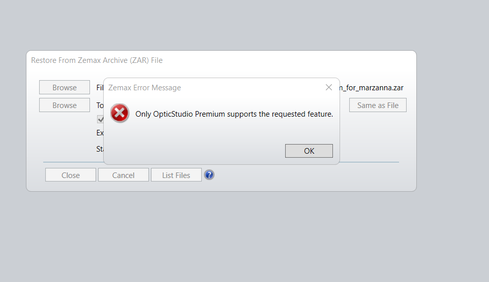
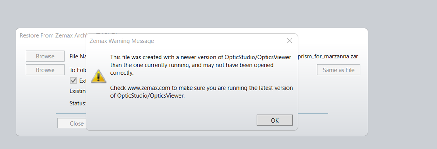
Thank you for taking the extra step in the attempt to solve my problem. I will carefully follow your work posted here. Unfortunately, I couldn’t fully open your file due to not having a premium version of Zemax but a pro version. So I got this
I had this problem before and found a solution following this post
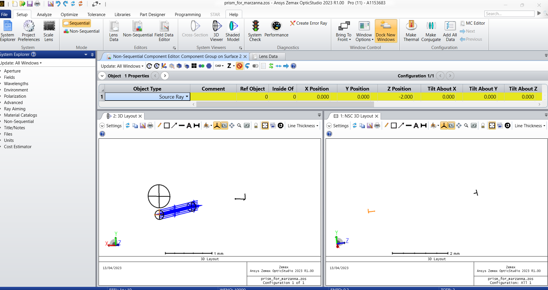
This is where I came to with my simulation ( I have attached file)
Still confused about the location of the entry and exit ports ( which one is one) and their different size, and what this arrow means (pointed by the red arrow). I am not sure if this is even correct.
Answering your question
First of all, I wanted my simulation to look more authentic with the right polygon mirror geometry and dimension. It looks more transparent for the audience to “read” from a simulation like this. As I am new to Zemax I did not realize the level of complication and this is my very first contact with NSC mode :)
Are you using two different version of OpticStudio? The Zemax Part Designer is only available in the Premium edition, but I assumed you had it since you sent me a screenshot of it. I think what is happening is that someone has generated the polygon with a Premium edition and converted it to *.IGS so you could use it in your Professional. Anyway, I think you’ve found the workaround yourself.
About the Entry/Exit port, have you looked at this article? The Help File (F1) also has detailed information in the section: The Setup Tab > Editors Group (Setup Tab) > Non-sequential Component Editor > Non-sequential Overview > NSC ray tracing in mixed mode (with entry and exit ports).
The Entry port is the aperture through which sequential rays are allowed to enter the Non-Sequential Component, and is defined by the Non-Sequential Component Surface itself. That is why we added a Z Position to the polygon. Without a Z Position = 2.0 on the polygon, this is what the 3D Layout looks like:
As you can see, the entry port is inside the polygon and the rays ignore the first surface of the polygon. This is because eventhough the polygon appears to intersect the rays before, those rays only enter (and therefore see) the Non-Sequential Component from the Entry port. If we wre to propagate those rays, they would reflect from the surface of the polygon after entering through the Entry port and stay trapped within the polygon:
Similarly, the Exit port is the only place where rays are allowed to exit the Non-Sequential Component and continue in the rest of your Sequential system. If no ray makes it to the exit port, then you won’t see them propagate through the rest of your system.
The issue with your system is that the incoming rays overlap with the ones that are reflected by the polygon, and you don’t want the Exit port to overlap with the Entry port (otherwise the rays enter and exit the Non-Sequential Component right away), which is why I had to move the Exit port to a different location:
The arrow you are refering to is a local axis of a surface or object. People often use it to orient their surfaces and objects correctly. If you double-click on a surface in the Lens Data Editor and go to the Draw tab, there’s a checkbox called Draw Local Axis. You can toggle this checkbox and see what it does. Basically, it shows a local axis referenced to the corresponding surface (you can do the same with objects).
Why do you think your file isn’t right?
Its only my opinion, but in my modest experience, it is rarely a good idea to mix simulation and rendering. If I have to make a visual rendering, whether it be for a presentation or a figure in a paper, I’d do it outside OpticStudio. The ray angles don’t need to be exact if you just want to showcase your model. Also, OpticStudio is not the best tool to produce good visual rendering. If anything the color options are quite limited. And on the flip side, a simulation might turn out to be computationally intensive, and you want it to be as light as possible. The more complex a simulation becomes, the harder it is to also interpret the results. Therefore, for a simulation, I’d always try to have a simple a model as possible, and complexify it if the need arise. Again, this is just my opinion, and I’m always happy to help anyway if you want to continue down that route.
to import a file made in Part Design I need to have it in the NSC component editor “CAD part: Zemax Part Designer”, which I do not have because it is only in the premium version. Based on this I assumed to have a premium version. Besides I have been using Zemax for the last month so I know a little about it, but for sure I was working only on the same version of Zemax.
Regarding the file I have sent you, I don’t know whether this simulation was right or wrong, I guess I got beginner's insecurities :) . I also think I will run the polygon mirror simulation in sequential mode, I was trying to overdo it making it more complicated than it had to be.
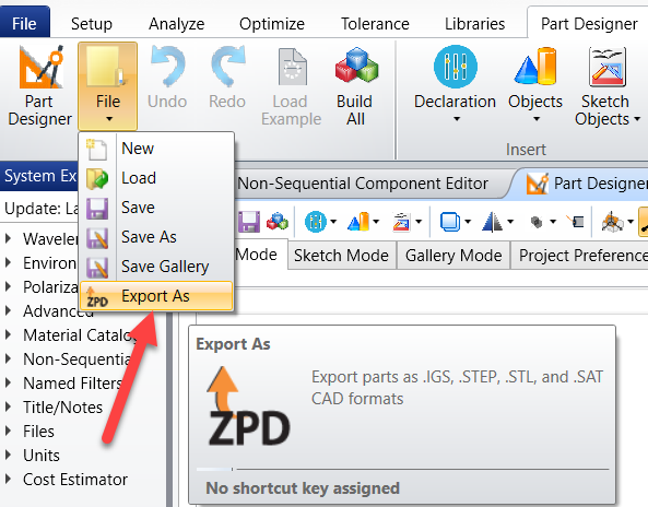
You can create a Part Designer with a pro version but you will have to export it as a STEP to use it. Only the premium version allows Part Designer objects.