I am confused about how the direction is calculated after determining the phase profile. The article says the cosine of the derivative of the phase difference is added. But that difference is not between -1 and 1 in most cases. For example, if wavelength=400, p=1, p^2 coeff = 1, the change of direction is 400/(2pi) > 1. Can someone explain where I am going wrong here?
Best answer by Jeff.Wilde
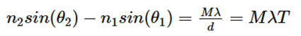
First, it’s important to note that the article you reference has a notation error. At the very beginning, when discussing a diffraction grating, it says that T is the period of the grating -- but if you look at the first equation, T is the grating frequency and d is the grating period.
To answer your question about ray propagation through general phase surfaces, we have to start with the concept of a ray in three-dimensional space as being described by its direction cosines (L,M,N). If you think about a unit vector pointing in the direction of a ray, the direction cosines are nothing more than the x, y & z components of this unit vector. Mathematically, the direction cosines have values given by the cosines of three angles between the ray vector and the x, y & z axes, respectively (so their values must lie between 0 and 1). However, I prefer to think in terms of components of a unit vector. Only two of the components are unique, as the third can be found from the other two because we know the length of the unit vector equals one. So, for example, if we know L & M, then N = sqrt(1 - L^2 - M^2).
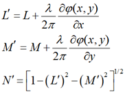
Now for a phase surface (i.e., a surface described by a phase function having units of radians) that is defined across some plane that is perpendicular to the z-axis, let’s call it phi(x,y), an incoming ray is deflected in accordance with the gradient of this phase function. Specifically, the direction cosines of the outgoing ray (L’,M’,N’) -- which again are simply the Cartesian components of the unit vector pointing in the direction of the outgoing ray -- can be determined from phi(x,y) and the direction cosines of the incoming ray:
The use of direction cosines to describe ray propagation is fundamental to ray tracing (see, e.g., What is a ray?). In this case we note that the phase gradient terms are bounded because any one of the outgoing direction cosines cannot take on a value that exceeds one, otherwise the ray cannot physically propagate.
Hope this helps…
Regards,
Jeff
PS: In OpticStudio, phase surfaces have a diffraction order parameter. This is simply a scaling factor that is applied to the phase function. For example, a simple diffraction grating can be modeled as a linear phase slope surface. If the diffraction order is n, then the phase slope is increased to n times its original n = 1 value. This results in the outgoing ray being deflected by a larger angle that simulates nth-order diffraction.
First, it’s important to note that the article you reference has a notation error. At the very beginning, when discussing a diffraction grating, it says that T is the period of the grating -- but if you look at the first equation, T is the grating frequency and d is the grating period.
To answer your question about ray propagation through general phase surfaces, we have to start with the concept of a ray in three-dimensional space as being described by its direction cosines (L,M,N). If you think about a unit vector pointing in the direction of a ray, the direction cosines are nothing more than the x, y & z components of this unit vector. Mathematically, the direction cosines have values given by the cosines of three angles between the ray vector and the x, y & z axes, respectively (so their values must lie between 0 and 1). However, I prefer to think in terms of components of a unit vector. Only two of the components are unique, as the third can be found from the other two because we know the length of the unit vector equals one. So, for example, if we know L & M, then N = sqrt(1 - L^2 - M^2).
Now for a phase surface (i.e., a surface described by a phase function having units of radians) that is defined across some plane that is perpendicular to the z-axis, let’s call it phi(x,y), an incoming ray is deflected in accordance with the gradient of this phase function. Specifically, the direction cosines of the outgoing ray (L’,M’,N’) -- which again are simply the Cartesian components of the unit vector pointing in the direction of the outgoing ray -- can be determined from phi(x,y) and the direction cosines of the incoming ray:
The use of direction cosines to describe ray propagation is fundamental to ray tracing (see, e.g., What is a ray?). In this case we note that the phase gradient terms are bounded because any one of the outgoing direction cosines cannot take on a value that exceeds one, otherwise the ray cannot physically propagate.
Hope this helps…
Regards,
Jeff
PS: In OpticStudio, phase surfaces have a diffraction order parameter. This is simply a scaling factor that is applied to the phase function. For example, a simple diffraction grating can be modeled as a linear phase slope surface. If the diffraction order is n, then the phase slope is increased to n times its original n = 1 value. This results in the outgoing ray being deflected by a larger angle that simulates nth-order diffraction.
Thank you for the explanation. Your answer clarified some of the issues that I faced. I understand that the direction of the ray is defined using cosines for each x, y, and z directions. However, when I try to manually calculate the direction using pen and paper, I come across the following issue where I’m not able to get the scaling correctly.
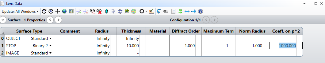
Let working wavelength be 400nm. If there is a “Binary 2” surface with semi-diameter 1mm, with diffraction order M=1 and phase profile coefficient for 2nd order be 1000 and let other orders be 0. I have a system like this.
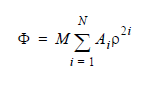
Now I want to calculate how much the ray bends when a ray comes at y=1mm perpendicular to the surface. I can calculate the phase derivative using the equation given in this article (What is the normalization radius?).
Where rho is the radial distance. Then we get derivative of phase w.r.t y axis as,
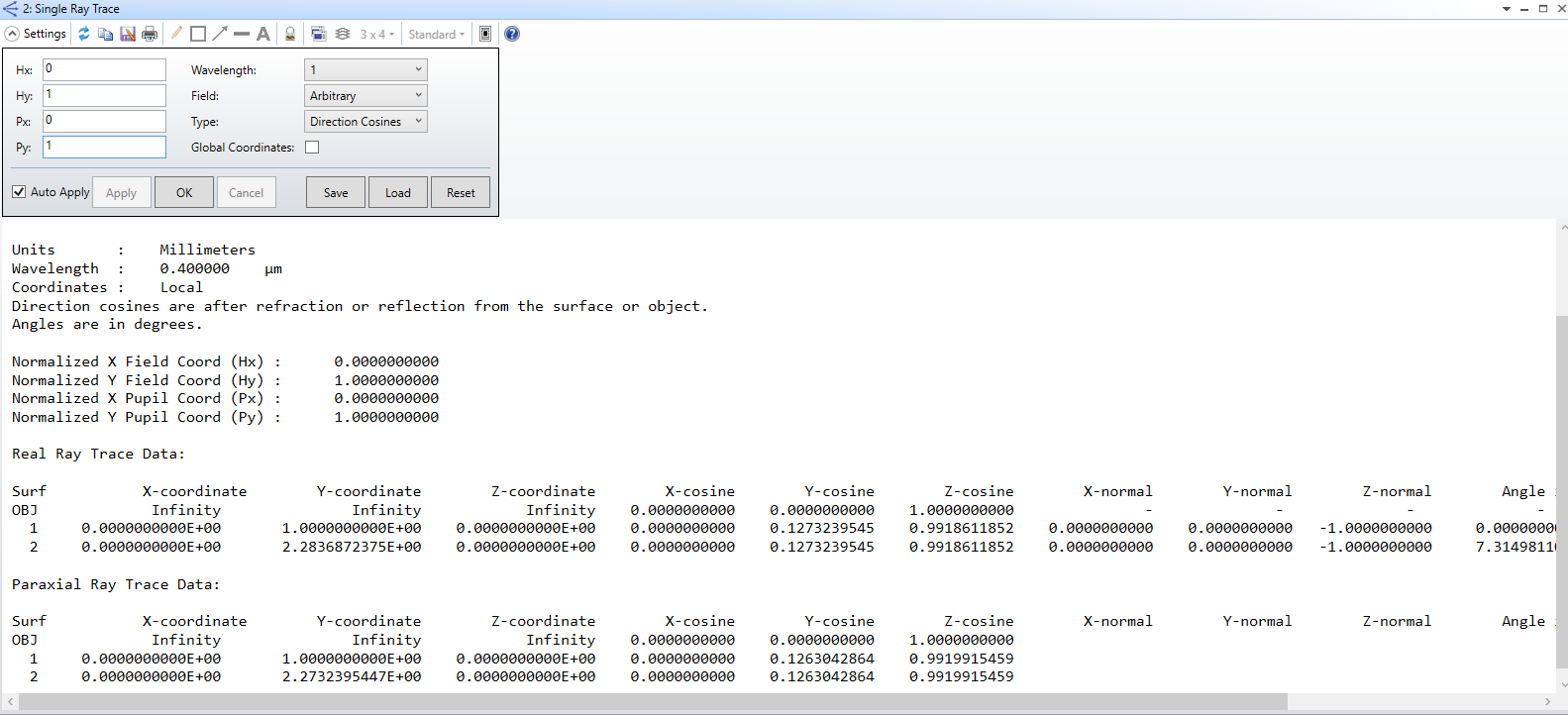
Then when we calculate the M’ we get,
When I look at the ray trace in Zemax I can see 0.12732 for the y-cosine which is 1000 times the value that I get.
I just realised it is from the R in the denominator. 😄
I will keep the reply so that someone may find it helpful.
By the way, if we change the shape of the surface, why does it affect the diffraction from the binary surface? In other words, does the diffraction due to binary surface depend on the surface normal?
Yes, in general for a tilted or curved phase surface, the angle of incidence at the ray-surface intersection point is needed to find the outgoing ray direction. When using the phase gradient equations, the direction cosines should be taken in a coordinate system with its z-axis along the local surface normal (at the ray-surface intersection point). The outgoing direction cosines can then be converted back to the local coordinate system in which the surface is defined.
You can see this with a simple linear diffraction grating. Consider the grating equation (the first equation in the Zemax article you cited). Both angles, theta1 and theta2, are measured with respect to the surface normal. If you use a diffraction grating surface in OpticStudio, and compare tilted and non-tilted cases, you will see that the outgoing ray direction cosine depends on the grating tilt angle.
First, it’s important to note that the article you reference has a notation error. At the very beginning, when discussing a diffraction grating, it says that T is the period of the grating -- but if you look at the first equation, T is the grating frequency and d is the grating period.
To answer your question about ray propagation through general phase surfaces, we have to start with the concept of a ray in three-dimensional space as being described by its direction cosines (L,M,N). If you think about a unit vector pointing in the direction of a ray, the direction cosines are nothing more than the x, y & z components of this unit vector. Mathematically, the direction cosines have values given by the cosines of three angles between the ray vector and the x, y & z axes, respectively (so their values must lie between 0 and 1). However, I prefer to think in terms of components of a unit vector. Only two of the components are unique, as the third can be found from the other two because we know the length of the unit vector equals one. So, for example, if we know L & M, then N = sqrt(1 - L^2 - M^2).
Now for a phase surface (i.e., a surface described by a phase function having units of radians) that is defined across some plane that is perpendicular to the z-axis, let’s call it phi(x,y), an incoming ray is deflected in accordance with the gradient of this phase function. Specifically, the direction cosines of the outgoing ray (L’,M’,N’) -- which again are simply the Cartesian components of the unit vector pointing in the direction of the outgoing ray -- can be determined from phi(x,y) and the direction cosines of the incoming ray:
The use of direction cosines to describe ray propagation is fundamental to ray tracing (see, e.g., What is a ray?). In this case we note that the phase gradient terms are bounded because any one of the outgoing direction cosines cannot take on a value that exceeds one, otherwise the ray cannot physically propagate.
Hope this helps…
Regards,
Jeff
PS: In OpticStudio, phase surfaces have a diffraction order parameter. This is simply a scaling factor that is applied to the phase function. For example, a simple diffraction grating can be modeled as a linear phase slope surface. If the diffraction order is n, then the phase slope is increased to n times its original n = 1 value. This results in the outgoing ray being deflected by a larger angle that simulates nth-order diffraction.
I also had some questions about diffraction grating surface, especially about notation (grating period, orders … and so on.). But now I got solved ! thanks a lot for your answers …
However, I still have a question about your reply - “If the diffraction order is n, then the phase slope is increased to n times its original n = 1 value. This results in the outgoing ray being deflected by a larger angle that simulates nth-order diffraction.”
I’ve thought a phase slope as kind of ‘phase gradient’ which is not wrapped to 0 to 2Pi. So I also have thought that the phase slope is designated automatically if we set the diffraction angle, incident angle, grating order, and wavelength of incident ray - by expression at the article
I want to know about phase slope term more exactly… why it becomes n times larger than before it is at the first order? could you explain about some details sir?
(p.s I have designed a simple diffraction grating surface - normal incident rays are diffracted to 45 degree after the surface along the y-axis. It is just linear phase gradient surface but has a different phase slope value, when I view surface phase cross section at tangential slope & angle 90 degree)
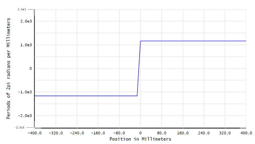
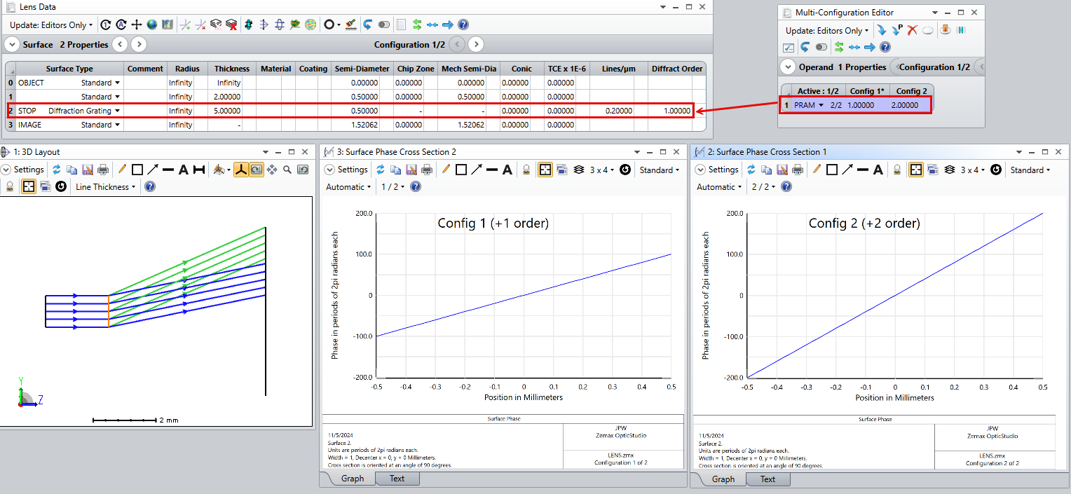
If you are trying to design a square-wave phase diffraction grating that mimics the physical structure of a real grating, it won’t work with ray tracing. Instead, you need to use a continuous phase surface that deflects rays as intended via the local phase gradient. For example, here is a Diffraction Grating surface modeled with two different diffraction orders (by using the multi-configuration editor):
You can see that in going from the +1 order to the +2 order, the phase slope used to simulate this surface doubles. If you need multiple diffraction orders at the same time, you may want to look at a non-sequential version of the grating.
We use 3 different kinds of cookies. You can choose which cookies you want to accept. We need basic cookies to make this site work, therefore these are the minimum you can select. Learn more about our cookies.