How can I design a microscope with two thick lenses in zemax? I want a magnifiaction of at least 2 for my system.

Solved
Designing a microscope
Best answer by David.Nguyen
Hi Sajed,
That is a pretty broad question. I’ll try to give you some clues and hopefully you can manage to achieve your goal.
Since you want to use two lenses, I’m assuming it is for an infinity system. In this case, the magnification is given by the ratio of the lenses focal lengths. If you want a magnification of 2X, you could use an “objective” (sample size) lens with a focal length of 100 mm and a “tube” (user or camera side) lens of 200 mm for example (200 / 100 = 2X). The longer the focal length, the longer the overall microscope. However, short focal length lenses typically have worst tolerances (they are harder to manufacture due to the curvature of its surfaces).
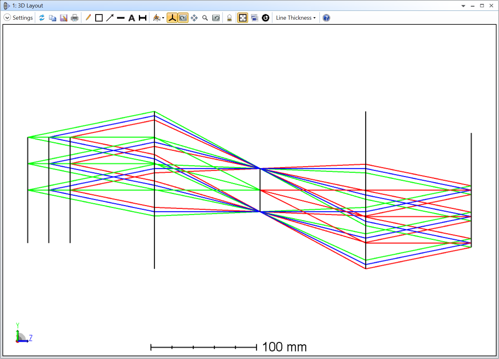
The other thing to keep in mind is the kind of resolution you’d like to achieve. In microscopy, people use the numerical aperture to compute an estimate of the resolution (have a look at this article). The longer the focal length, the smaller the numerical aperture for a given lens diameter, thereby limiting your resolution. In the example I’ve attached to my answer, I constrained the aperture STOP diameter to achieve a diffraction-limited design.
Once you’ve settled for the lens focal lengths and diameter, I’d browse the catalog lenses. In my example, I used THORLABS lenses (100, and 200 mm focal lengths).
The Merit Function in my example is just a spot criterion with two REAY and DIVI operands for the magnification. I take the ratio of the off-axis chief ray Y-coordinate in object, and image space as the magnification. I’ve added RAID operands to control the telecentricity of the system. It is not strictly necessary, but that is often the case in infitiy systems.
Note the orientation of the lenses, you typically want the more curved surfaces towards the parallel ray bundles.
Finally, there are so many more considerations when designing a microscope to be discussed that any forum answer would fall short to cover everything. As you progress with your design, I suggest you ask more specific questions when needed. This will increase your chances of getting a response.
Take care,
David

Enter your E-mail address. We'll send you an e-mail with instructions to reset your password.
Need more help?
To Chinese users:
Do not provide any information or data that is restricted by applicable law, including by the People’s Republic of China’s Cybersecurity and Data Security Laws ( e.g., Important Data, National Core Data, etc.).
不要提供任何受适用法律,包括中华人民共和国的网络安全和数据安全法限制的信息或数据(如重要数据、国家核心数据等)。