Hi!


I am supposed to design a Dragonian reflector system. The system is to be used at submillimeter wavelengths. It is to transform a Gaussian beam into a rotationally symmetric and collimated beam. According to my research group seniors it is possible to design such a system with a ray tracing software and afterwards tweak it such that it can be operated at terahertz band. However, my question is about design issues realated to the coordinate system. The sytem employs two off-axis mirrors, a hyperbolic subreflector, and a parabolic main reflector. (I have a couple of images attached). The paper, which these figures are taken from, fixes the coordinate system origin to the bottom left corner, at the optical axis of the main reflector. It gives exact formulas for distances, tilts, and offset angles. Is it possible to start a design in Zemax such that the coordinate system would be fixed and one could define all lenghts and angles with respect to that point instead of varying the direction of the z-axis between each mirror? Being able to fix the coordinate system, I could employ the formulas presented in the paper directly. I guess this can be done somehow utilizing the Local to Global function in the Lens Data editor, but when I try to apply this it gives me error message about invalid surface range.
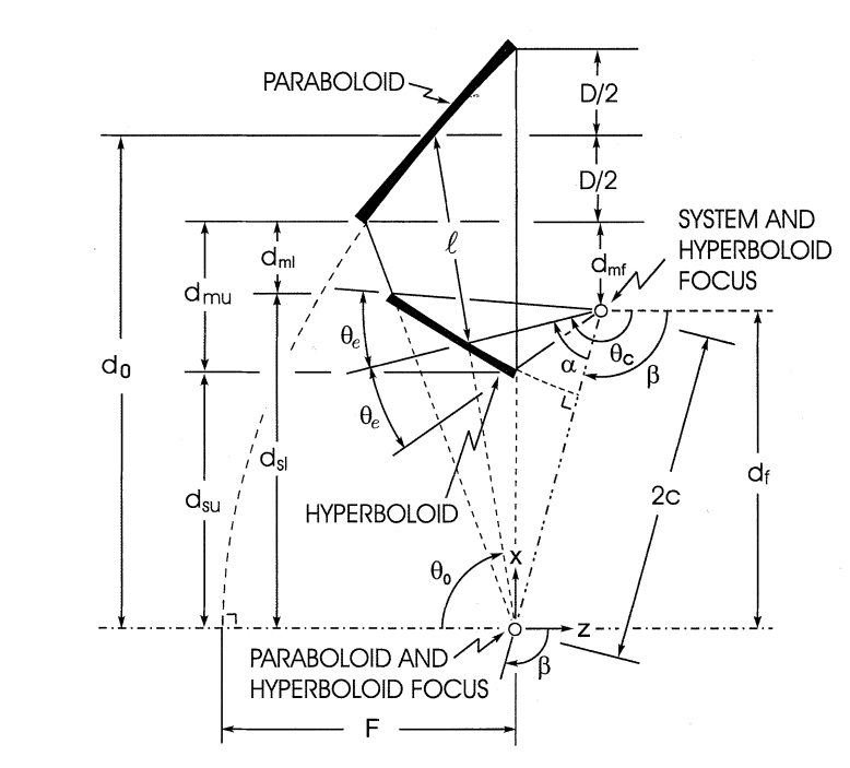
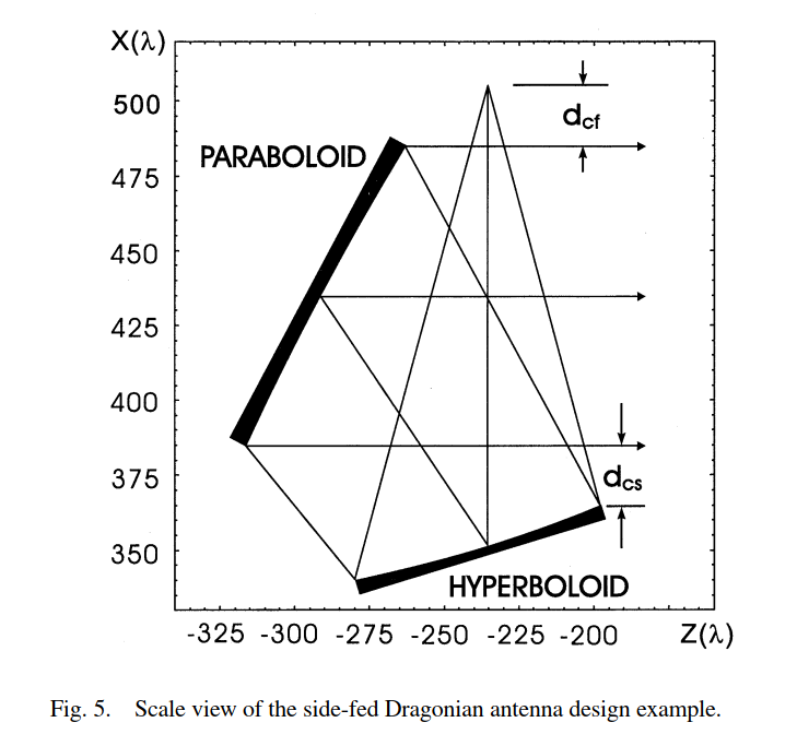


To our need, this side-fed configuration works best. In the upper figure, the configuration is front-fed, but it should not change anything. 


Thanks in advance for answering!


Best Regards,


Pyry


Is it possible to start a design in Zemax such that the coordinate system would be fixed and one could define all lenghts and angles with respect to that point instead of varying the direction of the z-axis between each mirror?


Yes. I would use non-sequential mode for this, use a null object as my coordinate reference and then position everything relative to that


Hi Pyry,


I would echo Mark's comments about Non-Sequential Mode.


The 'Local to Global' may also help. When using the tool, each element in the system is positioned relative to the reference surface by three coordinate break surfaces. The first coordinate break returns the coordinate system to the reference surface. The second coordinate break positions the group using the decenter x, decenter y, and thickness (z coordinate) relative to the reference surface. Finally, the third coordinate break rotates the group into the correct orientation. For the error on the 'Local to Global' tool, I would make sure:


  • the 'first surface' entry preceeds the 'last surface' entry


  • the first or last surface does not coincide with a Coordinate Break


  • the 'reference surace' entry preceeds the 'first surface' entry


  • no surface thickness, ignored surfaces, or any coordinate break properties within the range are controlled by the multi-configuration editor.


-Kaleb


Hi,


and thanks for your advice! I now managed to set up the design in non-sequential mode. However, I wonder how to simulate it. If I am not much mistaken, it can be done in the non-sequential mode but are the physical optics tools available for that mode? If I use the nonsequential group as a part of a sequential design, should I then have the physical optics tools? And should the Gaussian source and image plane or 'detector' (image space is afocal) be defined in the sequential mode?


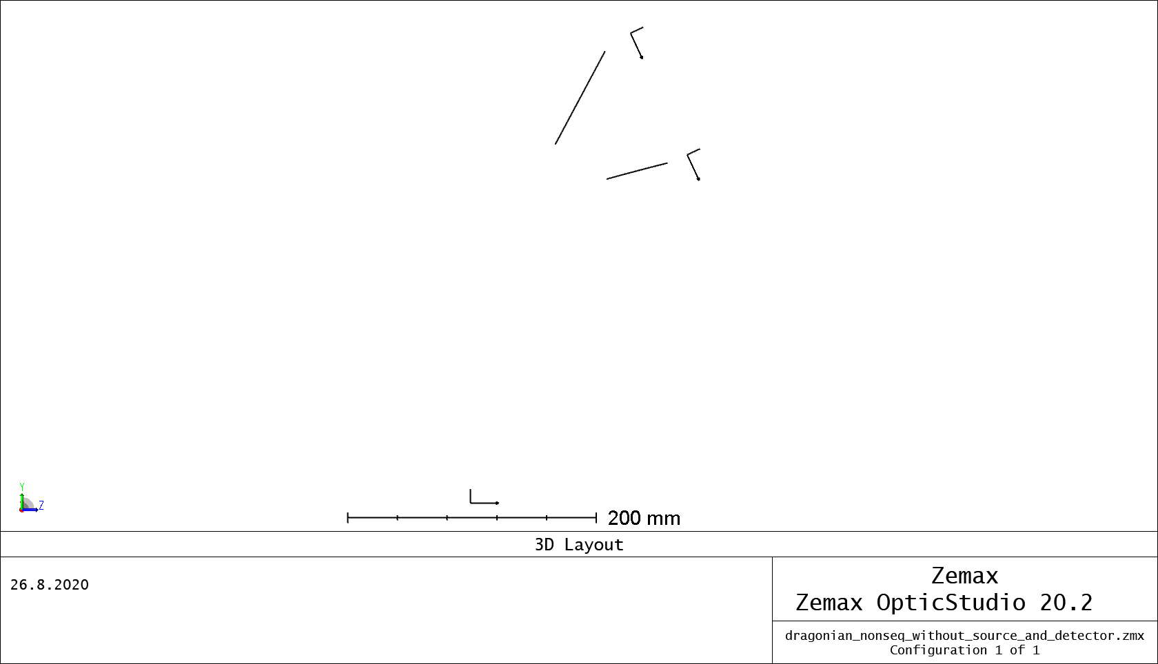
Another problem arising from moving back to sequential mode was defining the entry and exit ports. The sequential mode places the object relative to the nonsequential group origin. Is there any way I could change this into the nonsequential system focal point, which I have also defined as another null object? Atttached is the layout. Origin, system focus null object and subreflector optical axis are denoted.


Thanks in advance


Best,


Pyry


Hi Pyry,


There is currently no way to use Physical Optics in Non-Sequential Mode. The way you can do analysis in NS is by running raytraces and collecting the data on detectors. Here is an article that discusses this process: https://my.zemax.com/en-US/Knowledge-Base/kb-article/?ka=KA-01592#Introduction%20to%20nsrt


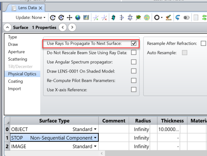
If you want to have a non-sequential component inside of sequential mode, it will have to start and finish with sequential surfaces. This means that the Object Plane will represent your source and the Image Plane will represent your detector. 


If you use POP in a mixed mode system, it will just propagate as rays through the non sequentail part. 


For defining the entry and exit port, I would recommend checking out this article:  https://my.zemax.com/en-US/Knowledge-Base/kb-article/?ka=KA-01678. This has detailed procedures on setting up a mixed mode system.


Please let me know if you have any other questions and I will be happy to help.


-Kaleb


Hey Pyry,


When I gave my advice to use NS mode, it was to make it as easy as possible to enter the coordinate geometry. But since you want to use POP, it's not that hard to set up in sequential mode: you just enter data in a local coordinate system, relataive to each surface, rather than the really flexible NS environment.


I'd do a ray-trace in the NS system of a single 'gut' ray to get all the coordinate data of that ray on the surfaces of the NS system. In the sequential mode, you'll just need two parabolid mirrors, and then use the tilt/dec element tool twice (one per surface) to orient the mirrors correctly. The math to get it set uip is a little trickier than NS, but it will work just fine and let you use POP or any other sequential tool.


Reply