Solved

Creating a stack of tilted concave mirrors (MEMS, DMD)

  • 20 October 2021
  • 1 reply
  • 364 views

Badge

Hello:

   I am designing an image slicer integral field unit for a spectrograph.  The image slicer is a stack of thin mirrors, all with the same curvature, but each individually tilted.  In my case, I have a stack of 24 thin mirrors, each 5 mm wide and 0.2 mm thick.  The whole stack of mirrors is about 4.8 mm tall.  Each mirror is tilted slightly from the one above or below it, like a pile of books on a table.  Here what it looks like from the side:


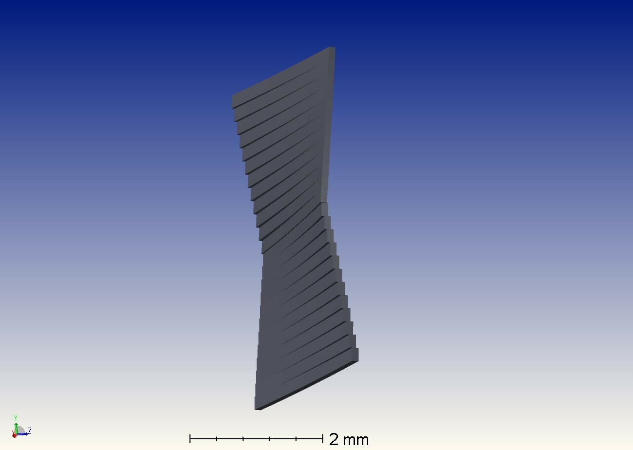
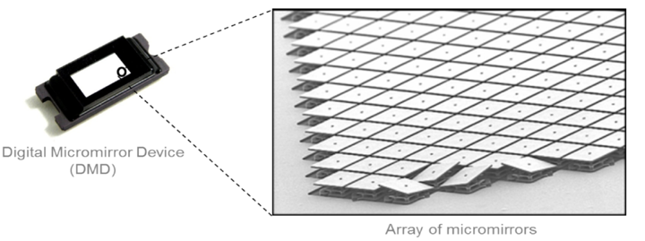
   I made this in Zemax using 24 different configurations.  Now I would like to make this as a single surface.  I would like to make a 1x24 array, and define an X and Y tilt of each mirror.    I’m told that the us_mems.dll user defined surface might be suitable to do this, but I can’t figure out how to use it to achieve my goal.  Specifically, I don’t know what angle0, angle1, angle2, rot angle, P flag, and Rows1-15 control.  How do I use the us_mems.dll to make a surface like this?  Thank you.


Cheers

Mike Connelley

icon

Best answer by David.Nguyen 20 October 2021, 19:04

View original

1 reply

Userlevel 7
Badge +2

Hi Mike,


I think what they call a MEMS in this DLL is actually a Digital Micromirror Device (DMD). It is an array of micromirrors, see image below from this document.

Each micromirror can tilt about a single axis and typically takes only two positions (plus or minus twelve degrees). As a side note, in the image above, the flat position adopted by many of the micromirrors isn’t typically achievable. Either the micromirror is tilted completely to one side or the other, and otherwise, it is considered to have a floating position (zero degree isn’t guaranteed), like when they are unpowered. Also note that the micromirrors generally tilt about the diagonal of the square surface they describe. The values A0, A1, and A2 from the us_mems dll are there to specify the available tilts for the micromirrors. For example, you could set A0 = -12A1 = 0, and A2 = +12, which would define three possible states for your micromirrors. The Rot Angle is the angle the micromirrors tilt about, when this value is zero, they seem to tilt about X. It is common for those devices to tilt at about 45 degrees so you would set Rot Angle = 45P Flag and Rows 1-15 is a bit more complicated and is explained here. Basically, it is how you specify which mirrors should be in which state (A0A1, or A2).

As such, I don’t think you can use us_mems directly to solve your problem since it doesn’t apply a radius of curvature to the mirrors (to the best of my knowledge) and only has a fixed set of three different angles. I’m guessing the people that told you to use it as a starting point meant that you could reprogram it to do what you exactly want it to do. If you need help with that let the community know.

I hope this helps, and take care,


David

Reply