I tried adding a new coating to the coating library using your Coatings Tool, now the Coating Catalog is empty, and I can't display my lens design because I get the error message that the coating doesn't exist.
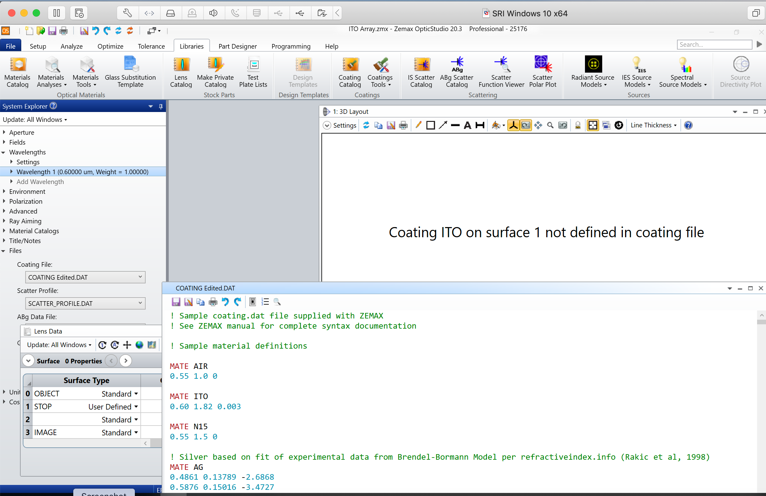
coatingnotdefined.png

Hi Karen,


The MATE Data Section defines materials that can be used to create a coating, but not a coating itself. These materials  can then be referenced in the COAT data sections. So, i.e. in your screenshot the material defined as air:


Is then used to defined a coating:


And therefore, you can apply this coating (GAP) to a surface in the coating cell in the LDE.


You can have a look at the coatings definition browsing the help file such as:


The Libraries Tab > Coatings Group > Defining Coatings


Thanks.  I figured that out right after I hit send.  I have another question, if I wanted to pattern the coating, is there a way to do that?  I've tried using the user defined surface us.array.dll, but I find there's no way to see what it looks like to see if I've defined it correctly.


Hi Karen,


Could you be more specific about what you're trying to do and how you want to view it? I'm assuming that patterning means to apply a coating in a repeating spatial pattern, in which case a DLL is probably the only way to go. But there are tools to work with coatings. What kind are you trying to pattern?


Correct, a spatially repeating pattern that leaves space between the regions that are coated.


Hi Karen,

Thanks for clarifying. As Kevin said, you can use a DLL to define the coating data, as it allows the definition of the s and p orientation complex reflection and transmission coefficients. The coating data can be based upon any data available within the DLL, including ray cosines, normal vectors, index, or other user defined data, or any other method that can be implemented within the DLL.For a source code example of how to define the electric field or coating data see the sample DLL US_POLARIZATION.

You may find useful this article that explains how to compile a User Defined DLL: https://support.zemax.com/hc/en-us/articles/1500005577602-How-to-compile-a-User-Defined-DLL

If working in non-sequential, you can use an object DLL(refer to the sample code Zemax\DLL\Objects\CoatingSample.c).

Depending on what you are trying to model, another possibility would be to use a nested surface or volume to account for the uncoated region.

Best,

Berta


I created a very thin version of my pattern in Part Designer and exported it as both .igs and .step files to try.  The glass catalog doesn't allow for entering complex index of refraction, so I entered the real part as the index and entered transmission values as a function of wavelength at a thinner sample. When I use this surface in non-sequential mode, will it all be imported the way I expect (designed in Part Designer - with the correct index), and will diffraction effects be handled correctly or do I need to use sequential mode and add it as a coating to look at diffraction effects?


Hi Karen,


You won't able to simulate the coating with an imported .STEP file in sequential. If you want to use this mode, you will need to write your DLL. However, you can use this object in Non-Sequential, just need to make sure that you are placing it in contact with the object that you want to coat


I know you can't use .step files in sequential mode.  The question was  does non-sequential mode take diffraction into consideration, or if that's what I want to investigate, do I have to switch to sequential mode? It sounds like the answer is I need to figure out how to create my coating with a .dll and use sequential mode.


Hi Karen,


No, diffraction is not 'naturally' taken into account in Non-Sequential Mode. There are diffractive objects in NSC but these are programmed to have an effect on the ray, but diffraction on travelling through multiple apertures is not supported. So, as you said, I'd recommend you to model your pattern coating in sequential.


Best,


Berta


Reply