I am Akhil, student doing master thesis. As a part of my work, I am using non-sequential mode in Zemax to develope the flourescence profile of the laser rod. Inside the laser pumping chamber, there is a metallic reflector and I want to simulate it for different material such as Aluminium and Steelon it. I have the CAD model of the reflector and can someone suggest me that how can I do that exactly?
Thanks in advance
Akhil
Page 1 / 1
You can use the material “mirror” for a simple aluminum coating.
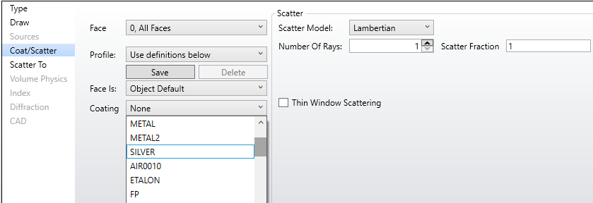
For more advanced materials, you can go to the object properties, in the “Coat/Scatter” tab and have access to more coatings. To define your own, refer to the manual on how to edit the coating file.
Thanks for your response,
I am working on the wavelenrth range of 808nm. In that particular wavelength range, the Aluminium has almost 86.7% reflectivity and Steel has 56.258% reflectivity. I am also working with the Gold coating as well, but I found the option to select the material ‘Gold’ from the coating options. Specifically, is there any method to allocate the particular value of reflectivity for the CAD model ?
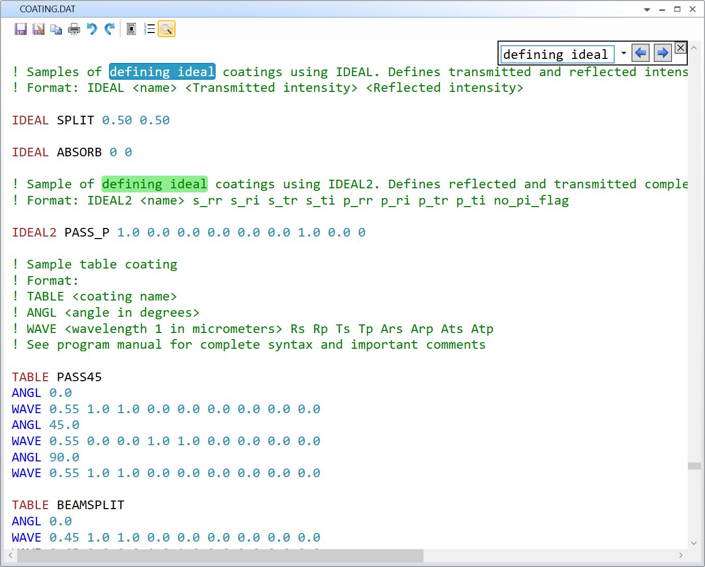
Regarding your specific question. Yes, there is a possibility to control the reflectivity of your CAD, and I believe you could use an IDEAL coating for that purpose. An IDEAL coating is defined in Librairies..Coatings Tools..Edit Coating File. The syntax looks like so:
Samples of defining ideal coatings using IDEAL. Defines transmitted and reflected intensity, rest is assumed to be absorbed Format: IDEAL <name> <Transmitted intensity> <Reflected intensity>
And this is an example of a dummy coating with 50% transmission, 25% reflection, and the rest (25%) is aborption:
IDEAL CUSTOM1 0.50 0.25
The IDEAL coatings are located near the end of the coating file, you can use the magnifier “Find Text” tool to reach it.
Let me know if this helps.
Take care,
David
Hi David,
Thank you for your response. I edit the coating catalogue file and try to simulate it. But is it necessary to enable the “use polarisation ” option when running the ray trace?
I tried without enabling this option, but the reflectivity changes between Aluminium and Steel didn’t made an effect in the result.
Hi Akhil,
You are absolutely correct. Here’s an excerpt from the Help File:
Use Polarization If checked, polarization will be used to determine ray energy, reflection, transmission, absorption, and thin film or coating effects
Does that make sense?
Take care,
David
Hi David,
Thank you so much for your response. That helped me a lot.
Akhil
Hi David,
If I am assigning an ideal coating like IDEAL CUSTOM1 0.01 0.97 ,for all the faces in the CAD model, then the 97% of the light is reflected in all value of wavelength. I my case, I assigned the wavelength as 808m , but still I should get 97% reflectivity.
When I simulate it with out enabling the Use Polarizationoption,then I got a total power of 3.5814E+02 Watts from the laser rod and when I enable the Use Polarization option, the total power reduced to 2,4258E+02 Watts. I believe that the power loss inside the laser rod is because of the polarisation dependence on reflection angle. Because both the horizontal and the vertical polarisation has different reflectivity for different incident angle.
Did I unserstood it in the right way?
Is the power loss is because of the exact reason that I assumed?
If my idea is right, then from what reference value zemax decide the refelctivty of the different polarisation? Does zemax has a reference diagram or datavalue for that?
Thanks is advance
Akhil
Hi Akhil,
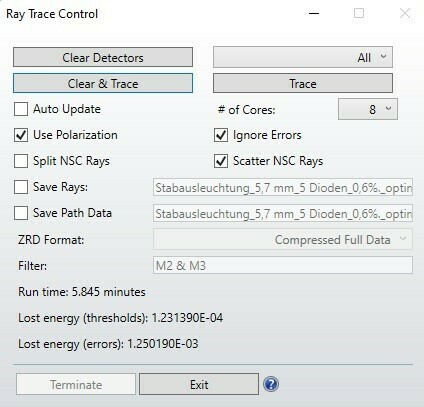
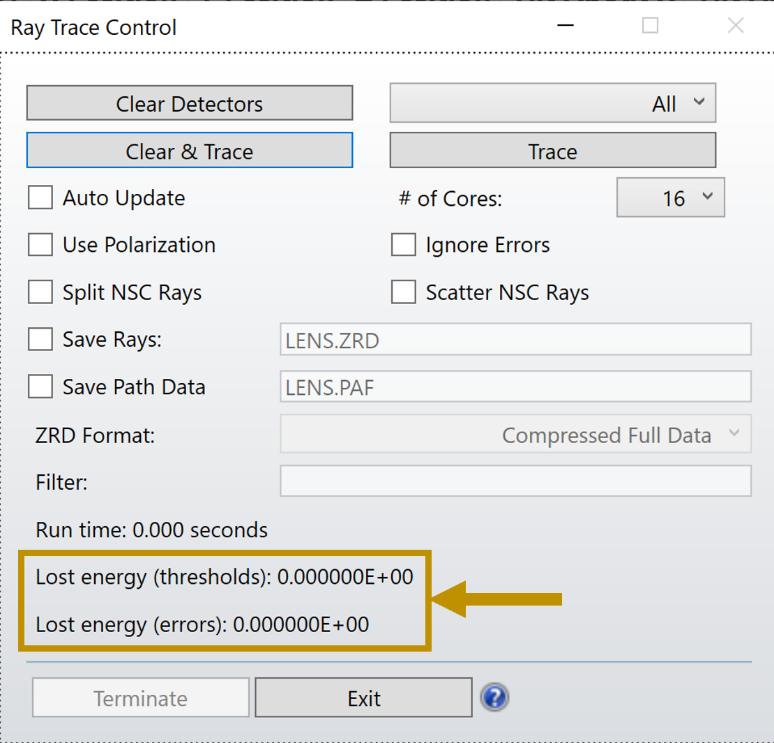
The IDEAL coatings should be independant of the incident angle. Can you check the Energy Lost in the raytracing?
And you should also check that your detector recieves the number of rays you expect.
Just to make sure you are not loosing energy somewhere else.
Can you share a simple example that demonstrate your issue?
Take care,
David
Hi David,
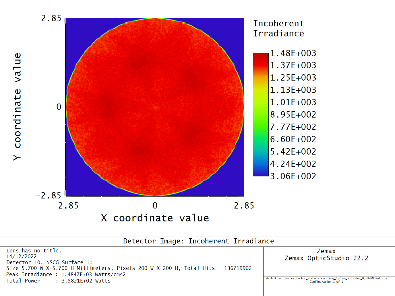
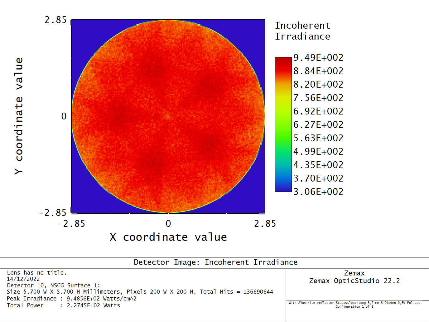
I am attaching two detector images that simulated by using the ideal coating IDEAL CUSTOM1 0.01 0.87 .
In this detector image, I didnt enable the Use Polarization option.
In this simulation, I enebled the Use Polarization option.
By analysing both the detector image, you can find the considerable difference in the total power inside the laser rod.
I hope this will help you.
Thank you
Akhil
Hi Akhil,
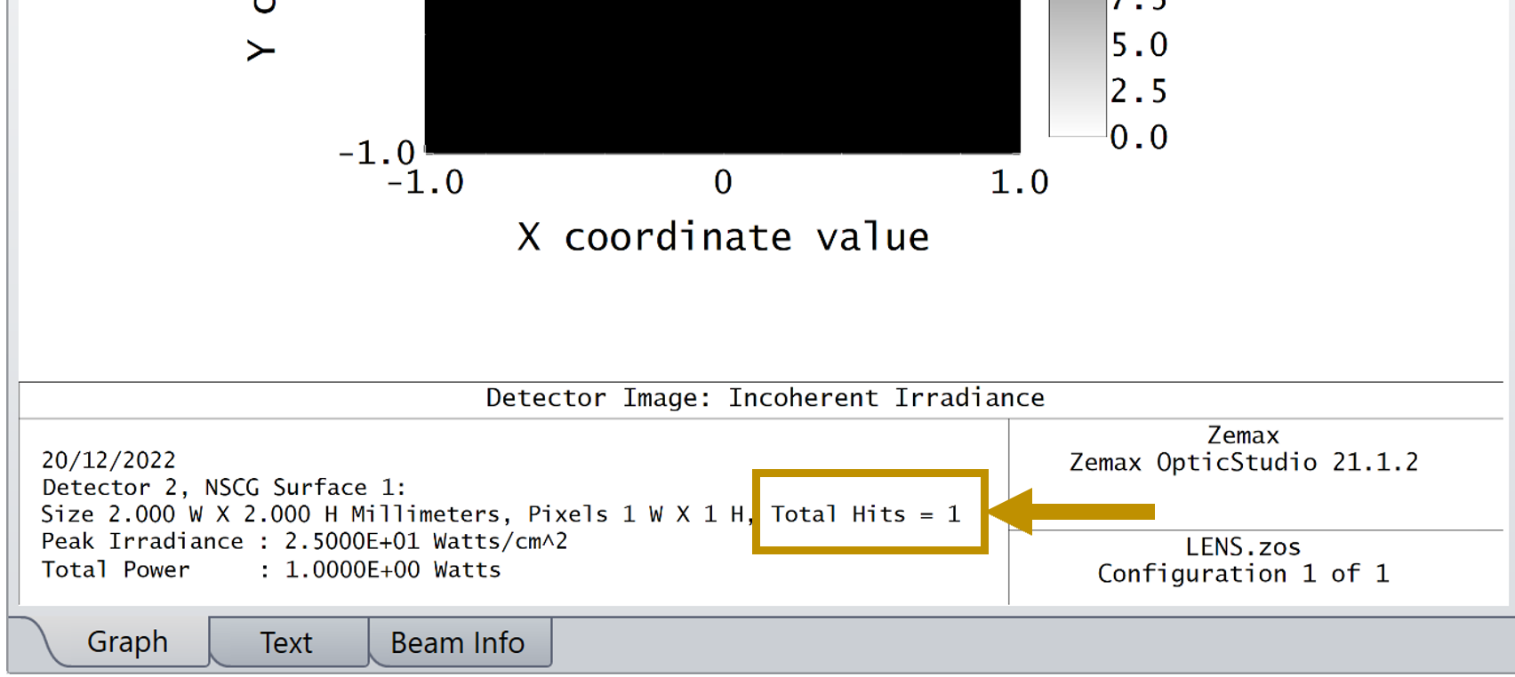
The Total Hits is different in the two cases. This means you are loosing some rays along the way and this is not due to the coating. If you have other interfaces in your system, I suspect those will be sensitive to polarization. Can you remove your IDEAL coating, and run a raytrace with and without polarization? What does it give you? Is there already a difference?
Take care,
David
Hi David,
The aim of the simulation is to increase the power inside the laser rod by using metallic reflector. So, for this purpose, three different metallic reflectors made of gold, aluminium, and Steel is considered because these material shows high reflectivity for the pumping wavelength 808nm (The pumping diodes have s-polarisation). The material has 97%,87% and 56% reflectivity respectively.
(1)
So, I made the three ideal coatings with the corresponding reflectivity values and checked the simulation results (Fluorescence by the laser rod) by considering the polarisation and without. Both time I got two different values for the total power inside the laser rod. Also, the Total hits is greater without considering the polarisation.
But when I checked the same without the metallic reflector, the simulation with the polarisation consideration shows the same power behaviour, but the total hit is greater in this case compared to without polarisation.
(2)
Also, I simulate the model with three different coating without considering the polarisation. But the reflectivity change of the material is doesn’t reflect on the total power value from the detector image. In all reflector material simulation, the total power accumulated on the laser rod is almost similar.
(3)
So, I am still confused that in which way I should analyse my simulation results. From the reflection from the metallic surface, each polarisation component of the light will get different amount of refection according to the incident angle on the metallic reflector (Theoretically). So, I should consider this to analyse the result. So, I should consider the polarisation option in the simulation or not??
I attached the file along with this and hope that this will lead to you a better solution!!