I am trying to model a system as seen in the diagram below where the black line is a circular reflector and the pink lines are the rays coming out of the pink dot. Can I have some insight on how to model this system? I would also like to vary the radius of this circular reflector and the distance from the pink dot to the vertex of the circular reflector.
I would really appreciate any help and thank you in advance!
Best answer by David.Nguyen
Hi Apena,
In sequential mode, you can:
Change the material cell of the mirror surface to MIRROR
Apply a Radius to this mirror surface (which can be made variable)
Change the Thickness to the mirror surface (which can also be made variable: pink-dot-to-vertex)
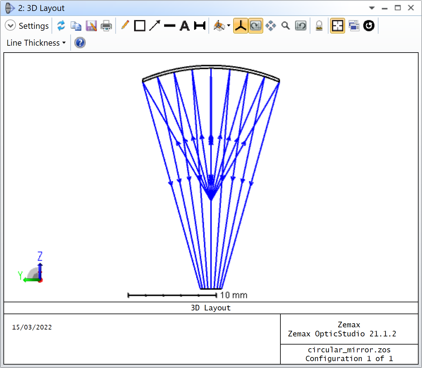
I’m attaching an example that looks like so:
I hope this helps. If you haven’t already, I would also recommend checking the Getting Started articles.
This really helps! I just wanted to solidify my understanding. In the Lens Data Window, the OBJECT’s radius affects the circular reflector’s radius and the STOP’s thickness affects the distance between the source point (pink dot) and the circular reflector’s vertex?
As a follow up, why does Clear-Semi and Mech-Semi Diameter change automatically? Should I be manipulating these values as well?
You are correct about the radius, but the distance between the pink dot and the reflector is controlled by the thickness of the OBJECT surface. Think of your pink dot as the OBJECT, and the STOP is the reflector (it doesn’t have to be the STOP, but it just so happens in this example).
The Clear Semi-Diameter will automatically adjust to the marginal ray distance with the optical axis by default. You can give it a size if you like. If you do so, you’ll notice a letter U in the cell on the right of the Clear Semi-Diameter and on the left-most column of the lens data editor, on the same surface, you’ll see a caption (aper) has also appeared. It means the Clear Semi-Diameter is now fixed and its aperture is controlled by the value specified by the user. Rays might get clipped when going through this surface if they don’t make it through the aperture.
The Mechanical Semi-Diameter can be understood as the actual physical diameter of the lens. It includes any margin the user would like to have to mechanically hold the optics in place. Have a read at this article. You are also free to define it yourself. Otherwise, it is automatically matched with the Clear Semi-Diameter. Typically, if you use a lens with 25 mm diameter, it will have a clear aperture that is smaller, say like 21 mm diameter, allowing for 2 mm mounting space around the lens.