Is there an easy way to check the pixel number being referenced in the merit function editor? Based on the numbering convention described in the help file, I *think* I’m referencing the pixel I want, but I’d like to do a sanity check. Eg: I want the pixel in thee lower left corner at 85% of the field of view for a 200x200 pixel detector. Based on the numbering convention, I *think* I want pixel number in the row starting with pixel number 15x200 = 3000, then, 15 pixels in, so 3015.
I would like to check this. For example, if there were a way to trace a single ray that hit the detector at pixel number 3015 and show it on the detector viewer, this would suffice.
Any thoughts, hive-mind?
Page 1 / 1
Hi @Big-ted,
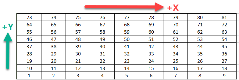
One thing that I think is not explained in the Help File and is worth knowing (althought perhaps obvious to some people) is that the convention that they describe:
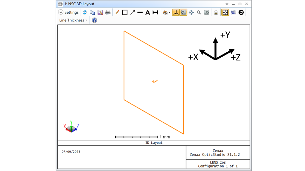
is valid in the local axis system of the Detector Rectangle. You can view the local axis of your Detector Rectangle in a 3D Layout by double-clicking on this object in the Non-Sequential Component Editor (open its properties) and navigate to the Draw tab. In the Draw tab, tick the Draw Local Axis checkbox.
As you can see in my screenshot above, with a default Detector Rectangle, because the local axis is aligned with the global axis, its actually alright. But things can get more complicated if you’ve turned your Detector Rectangle for some reason.
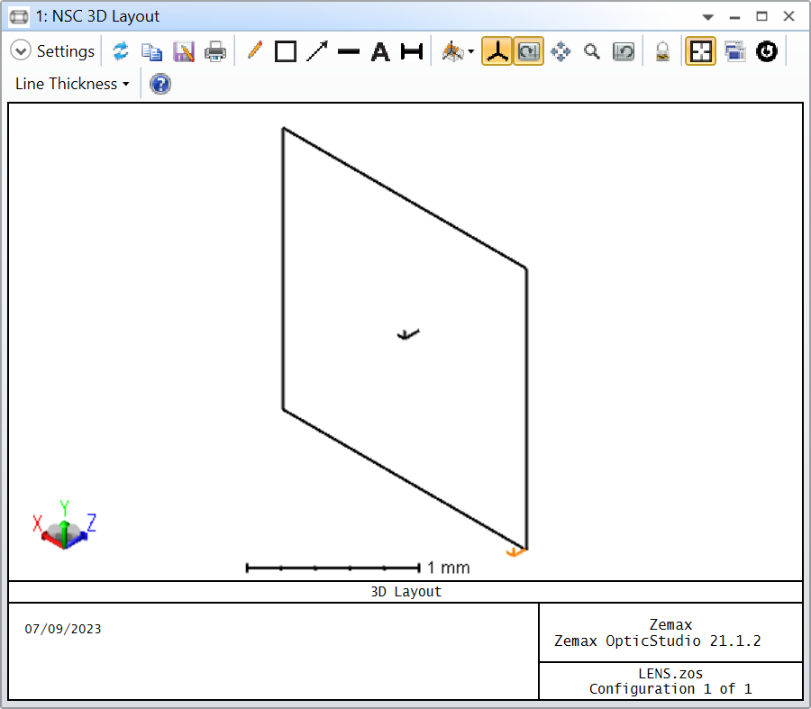
The procedure you describe for sanity check makes sense to me, and you can achieve it with a Source Ray. I’m showing an example with pixel number 1 first:
In this instance, my Detector Rectangle is a square with a half-width of 1.0 mm, or 2.0 mm full size. The Detector Rectangle has 200 pixels, therefore every pixel is 2.0 / 200 = 0.01 mm large. The pixel number 1 is at the smallest X, and Y position, which in the Detector Rectangle would be -1.0 mm, but that would be the very corner of the Detector Rectangle, I’ve just added 0.005 mm, which is the center of the pixel. Here is the result:
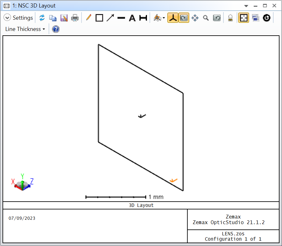
Lastly, you were interested in pixel 3015. I think there’s one thing to clarify. You want 15 pixels along Y, so you calculated 15x200 = 3000, which is fine. But, if you want to also move by 15 pixels along X, you need to be cautious. Remember you start a 1 (which is confusing), therefore you need to add the Y pixels, which leads you to 3001. Finally, you need to add 15 pixels to 3001, which gives you 3016. To verify, we know that every pixel is 0.01 mm, so 15 pixels is 0.15 mm. If we add 0.15 mm to X and Y of our Source Ray we get:
Pro tip: when you have the value -0.995 in the X column of the editor, instead of calculating -0.995 + 0.15 and inputing the value, you can simply select the cell with -0.995 and press +0.15. OpticStudio will automatically do the addition for you :)
Does that make sense? I hope it helps.
Take care,
David
I’d write a macro that clears all detector data and then sets the value of just one pixel. Then you can use the viewer to confirm that you’ve lit the correct pixel.
@Mark.Nicholson always on point!
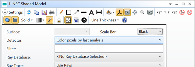
I could add that it is also possible to view the result in a Shaded Model if you set the setting: Detector to Color pixels by last analysis.
With this Non-Sequential Component Editor:
The following ZPL command:
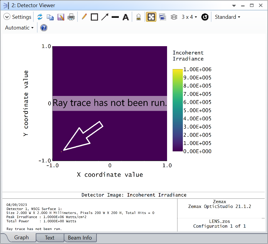
SETDETECTOR 1, 1, 3016, 0, 1.0
Gives the following results in a Viewer:
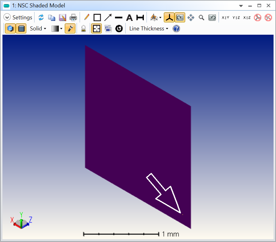
And this is the same result in a Shaded Model with isometric projection:
Take care,
David
Hmm. The ‘SETDETECTOR’ ZPL command looks like the ticket. More and more I find myself circling the rabbit hole of having to jump in and write my own macros, having avoided it thus far. I’ll have a poke around and see what can be done. Thanks for the input, both of you.
Hey Big Ted,
ZPL is really easy to learn of you’re not a programmer, so jump on in. If you are a programmer, then use the ZOS-API with your language of choice.