Solved

Cannot compute when chief ray cannot be traced

  • 26 May 2020
  • 6 replies
  • 1080 views

Hello!


I keep getting the error message:

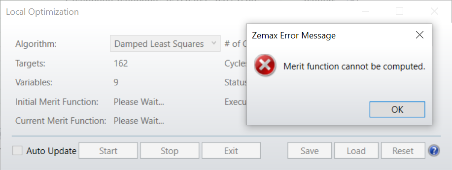
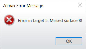
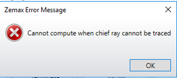
'Cannot compute when chief ray cannot be traced!'

during optimization using least squares method. The optimization interrupts and resumes once I click 'ok' or 'X' on the message pop-up window. 


  • Any ideas how I could interrupt at the point where the error-message pops up to investigate the cause?

  • Are there any options to automatically ignore this message and resume the optimization without having to click the message away manually?


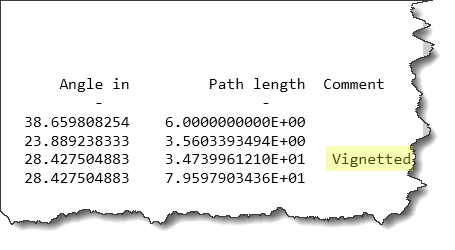
I am using the damped least squares optimization to optimize the shape of the example UD surface 'us_multizone_asphere' with two zones. I already tried different merit function operands without success. As it did not occur with simpler surface structures, I assume that some geometric surface constraints are required.


  • Any ideas how to approach this (e.g. setting appropiate geometry constraints...)?


Thank you!


Simon

icon

Best answer by simon.schroeder_01 2 June 2020, 16:53

View original

6 replies

Userlevel 2
Badge +1

Hi Simon, 


As you suspect, this error is quite often due to specific changes in surface geometries or element position. At their core, many of OpticStudio's analyses are based on calculations of chief ray parameters, so if the chief ray can't be traced (due to TIR, missing a surface, etc.), the analysis will also fail. That's likely case for you here, especially given that you're using the multisphere asphere .DLL. 


When you're seeing the error, how is it worded? Do you see a pop-up reading 'Cannot compute when chief ray cannot be traced,' or does that appear on one or more of your analysis windows? Generally when I see this during optimization, I'll see something like this:


This is followed by something like this:


If you're seeing an error message like one of the above, take note of the Target or Surface identified in the message. The Target specifically indicates the Merit Function operand that can't be computed, which can lead you to determining why the error exists. Check out this article for some more info on how to track these down: How to locate geometry errors: part 1.


In terms of constraining the surface geometry, takea look at this article: How to constrain the thickness of aspheric components. It'll get you started, but if you have some specific constraints you're looking to implement, let me know what you're trying to do in a little more detail, and I can provide some guidance as appropriate.


Cheers,


Nick

Hi Nick,


you understood correctly. Unfortunatly, I do not get such a detailed error message.


There is only a pop-up: 'Cannot compute when chief ray cannot be traced'. If I click it away, the optimization continues untill the same pop-up window shows up again or the optimization is completed.


Thanks for the article regarding constraints with aspheric components!


Cheers,


Simon


chiefray.png
Userlevel 5
Badge +1

Hi Simon,


Thanks for your follow-up here!


In truth, it's a bit hard to comment on what specifically the issue is without directly seeing the file. Is there any chance you could share the file here, preferably as a .ZAR (our archive format)? That way, we could take a closer look at it and make any further comments.


In the meantime, you could also try and do some more investigation using the Single Ray Trace analysis (Analyze tab...Rays & Spots...Single Ray Trace). If a ray encounters any error in the trace, it will be reported in the analysis, so it can be useful in assessing what's happening with your chief ray. It can also show the intercepts on a surface-by-surface basis, in case the real issue is that the chief ray is somehow missing a surface due to some defined surface apertures, for example:


Again, it's a bit tough to reproduce your specific issue (the first error message popping up without any subsequent messages appearing), so it would be helpful to have a file handy that reproduces your issue, even if it needs to be scrubbed of any proprietary/sensitive information.


Please let us know how these thoughts work out for you and whether or not you can share your file here. Thanks for your time! Hope you have a great rest of your day.


~ Angel


Hi Angel, Nick,


So far the problem was that the error only appeared during optimization and I could not get the optimization to stop at a point where the parameters reproduced this errors. By chance, I encountered a system that creates the same 'Cannot compute when chief ray cannot be traced' error message: The problem appeared to be caused by a singularity in the 'us_multizone-asphere' surface that occurs if the conic constant is too large (or the radius of curvature is too small). As a result, the surface steepness reaches infinity resulting in ray-tracing problems. 


Now, I included two constraints NORX<0.3 and NORX>0.0 at the surface's edge. So far, this seems to do the trick...


Have a great day!

Simon


Userlevel 6
Badge +2

Hi Simon,


Thank you for letting us know the problem! Adding boundary operands is definitely the right call here! When this type of error appears during an optimization, it is often the case that at least one of the variables in the system is changing too drastically and is causing serious ray vignetting or TIR. We provide many types of boundary constraints to help you control your variables. Some particularly useful ones are PMGT/PMLT (constrains extra data parameters), CVGT/CVLT (constrains curvature), and OPGT/OPLT (constrains operands in your Merit Function).


Since you found that the conic constant was the primary source of the error, you could also try constraining that with operands COGT and COLT:


Best,


Allie

Hi Allie,


yes, I am aware of these operands and they come in very handy at many places. However the maximum value allowed for the conic constants depends on the radius of curvature. As I also want to be able to optimize radius and conic at the same time, I decided to go with the NORX operand to directly adress the surface-steepness issue. Hopefully, in the future Zemax can provide a solution that avoids unphysical surface configurations from the get-go (including negative surface thicknes, overlapping optical surfaces,...).


Best,


Simon

Reply