I will be sending Support a (proprietary) .ZAR file demonstrating these two issues I just encountered in OpticStudio 20.3 (haven't tried this before, so I don't know if these are new or not).
Meanwhile, has anybody else encountered either of these 2 effects (in order of decreasing seriousness):
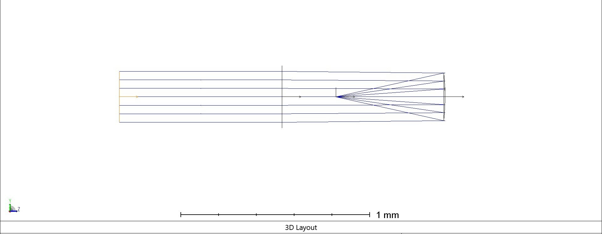
(1) For a concave mirror, I wanted to use a pickup solve from a Thickness (in this case object thickness on Surface 0) to the Radius of the mirror (Surface 1). I wanted to set R = -2H where H is the Object Thickness in order to approximately collimate the light (i.e. set the focal length of the mirror to equal the object thickness, make it concave to the left using a negative Radius).
Using a Solve Type: Pickup, I set From Surface: 0 (object) , Scale Factor: -2 (to make Radius = -2*H) and From Column: Thickness.
The Radius came out 1/2 the thickness, not 2x !! To get what I needed, I had to set Scale Factor: -0.5 ...only then will Radius = -2.0*H. ??!!
Could this have anything to do with the next thickness after the mirror being negative? (which I had to do to make the mirror work properly, i.e., for the Law of Reflection to work) I've avoided inserting Coordinate Breaks, because frankly, I couldn't figure out how to make my system work with any combination of 180-degree axis flips or negative signs on thicknesses.
(2) 3D Layout graphics window:
In the same model, which has small optical elements ~0.3 mm across, I used Project Preferences : Graphics to adjust arrow fletch size (which does not appear to be linear, but OK, I liked it at Fletch Size = 0.6. Fletch size 1 was way too big.
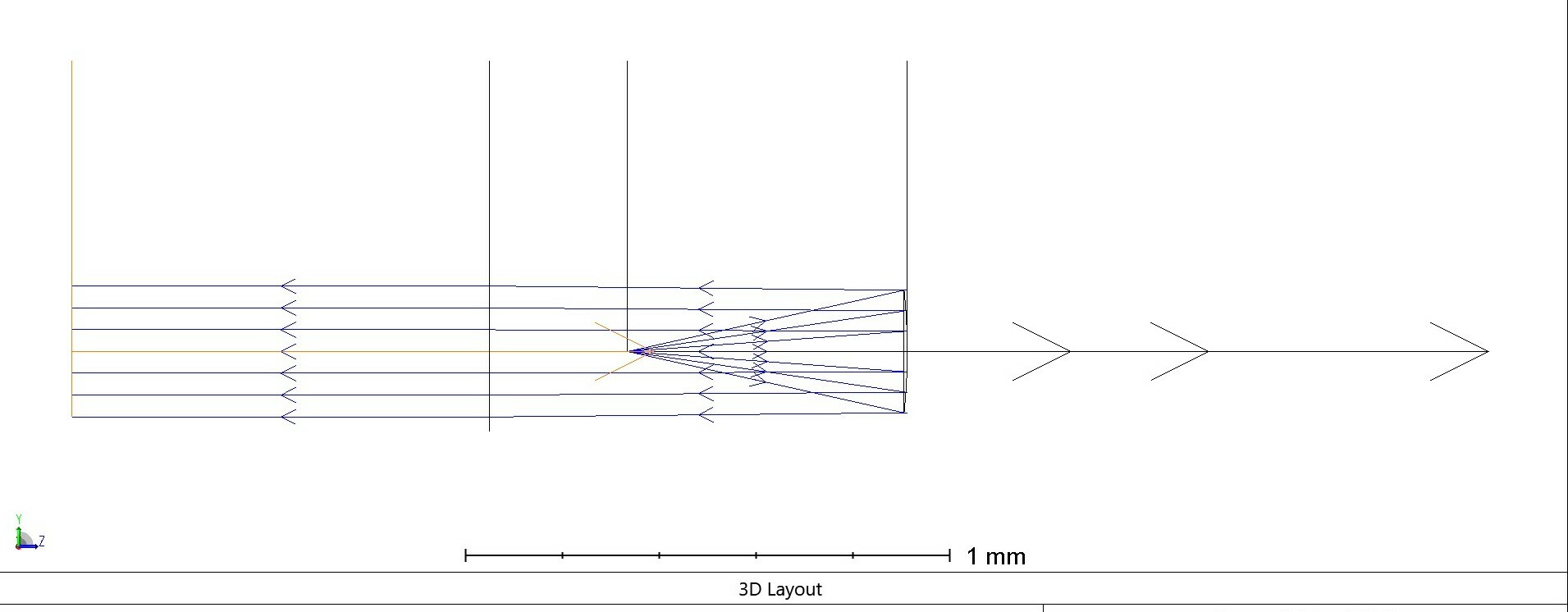
But as you can tell from (1), I needed to use Draw Local Axis a lot to try to figure out signs of propagation. Unfortunately, when I scale the model down to this 0.3 mm element size, the Local Axes don't scale down, and are WAY HUGE compared to the surfaces.
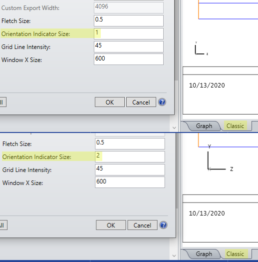
I tried adjusting 'Orientation Indicator Size' in Project Preferences : Graphics, (e.g. down to 0.01 from the default 1) but it has no effect on the Local Axis markers. Is it supposed to? Or is there something else that is an Orientation Indicator Size (I see no effect on the XYZ global axis markers in the corner of the 3D Layout window, either)? Or a different way to make the Local Axis markers smaller in the 3D Layout window, which is what I really want?
-- Greg


