Hi
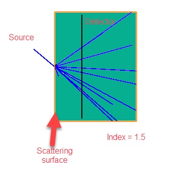
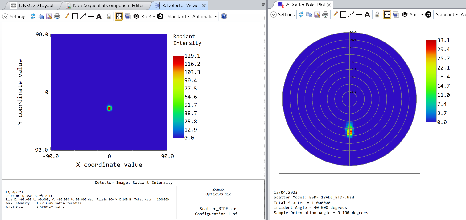
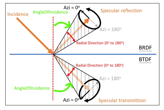
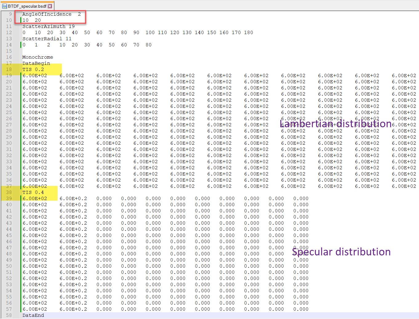
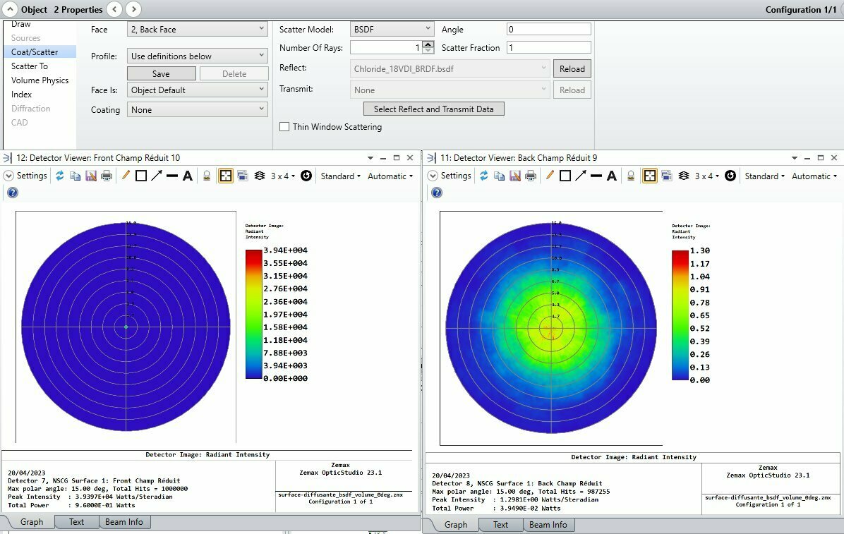
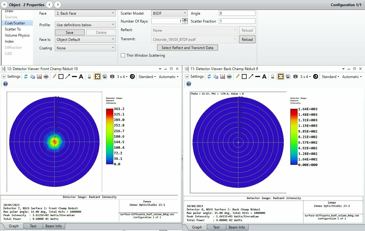
I try to make a BTDF data file to simulate a VDI roughness from air to glass or glass to air, but I don’t understand what is the reference for radial direction, it is indicated by the “angle of direct transmission” in article https://support.zemax.com/hc/en-us/articles/1500005486801-BSDF-Data-Interchange-file-format-specification
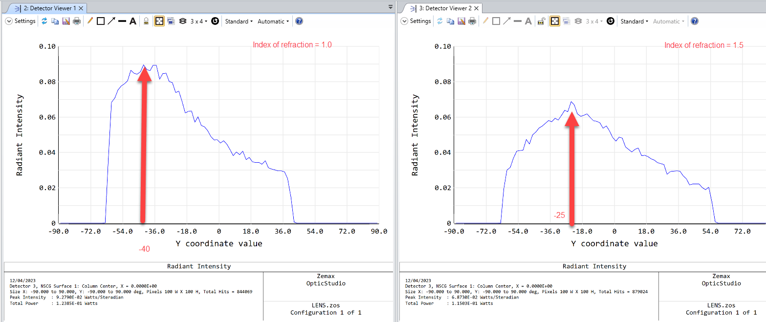
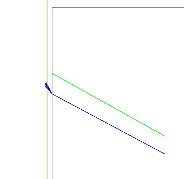
Do I have to take into account the refraction for this angle, which seem logical, or not ?
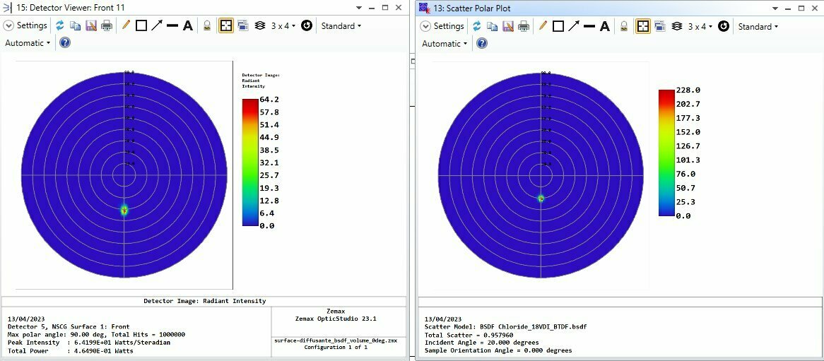
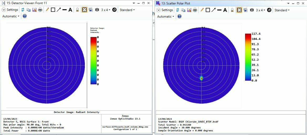
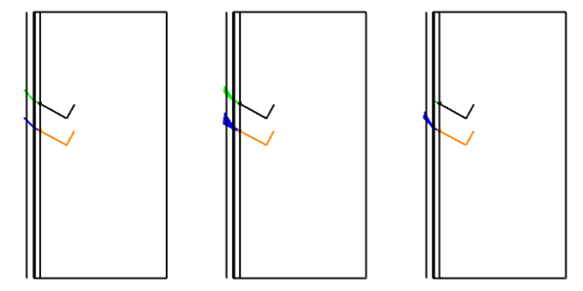
Is it possible do use BTDF scattering between two media with a difference on refractive indexes?
Marc