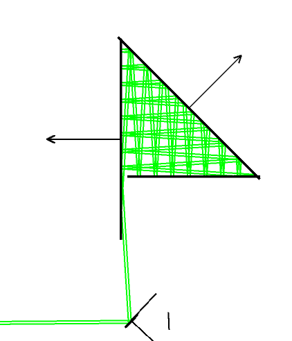
I’m trying to make a high power beam dump in the form of a triangle with a slit for the incident power.
The idea is that each surface should be X% absorptive and that the beam should bounce around between the three multiple times before enough of it’s energy dissipates.
I’m getting constant errors with either not enough segments, or geometry errors.
Also, I’m wondering if there might be a better way to “coat” it with a X% absorptive coat.
What I’ve been doing, is placing a very thin piece of glass in front of each detector and coating the glass accordingly.
Best answer by David
Hi Eli,
A few more comments. But please tell me if I’m over doing things!
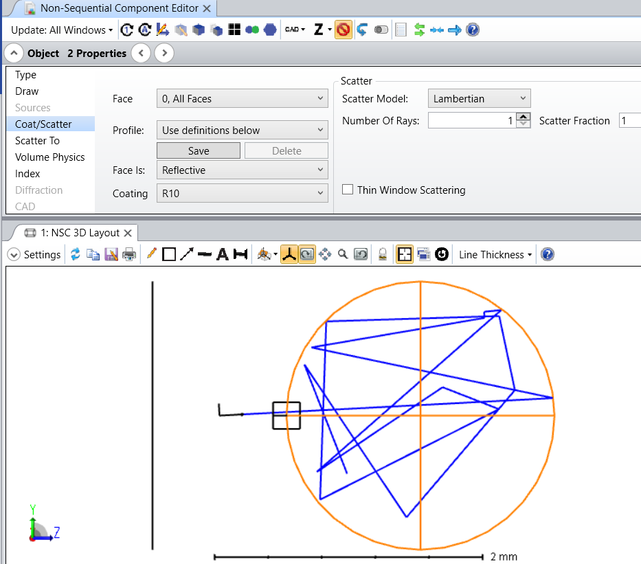
The point of controlling the geometric increase in child rays is to limit the number of ray segments that are killed for low energy, while assuring coverage by increasing the number of analysis rays. The attached file models an integrating sphere. The walls have a coating that reflects 10% while absorbing 90%. Lambertian scattering is added with a varying number of child of rays scattered. The input to the sphere is a Source Ray. The Minimum Relative ray is 1e-15. So after 15 reflections a single ray will be killed.
Here is one ray scattering 15 times with one child produced at each scatter:
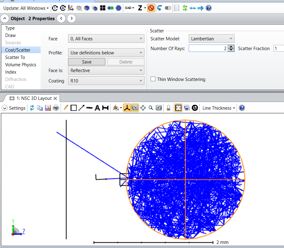
If we produce two child rays we get an extremely large number of rays, and many will have very low power. This is from only 1 ray launched. Edit: From a single ray launched we get 1.17e-13 W lost to thresholds.
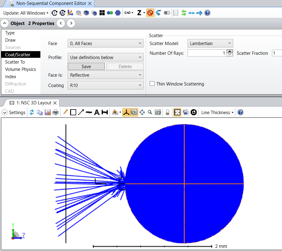
However, if we produce only 1 child ray per scatter, we can increase the analysis rays to 1000 and get this. Edtt: From 1000 rays launched we get 6.36e-16 W lost to thresholds.
In the first case we have generated an enormous number of child rays having 1e-15 relative power. In the second case, we wind up with 1000 child rays each having 1e-15 relative power.
The point is to control the geometric expansion of ray segments, but get adequate statistics by the number of rays launched. For scattering, controlling the number of scattered rays produced does this. For splitting, we can use Simple Ray Splitting to do the same thing. In the case of 1000 rays launched and 1 child per scatter, we know we will have 1000 rays each having 15 child rays, and only 1000 rays will be killed for having relative power below 1e-15. So we are in control!
And regarding the detectors. If the detectors are set to Front Only and oriented to detect only rays which go through them to strike the dump surface -- not those reflecting back -- then you know the power striking the surface. If you also know the absorption, then I think you can calculate the absorbed power. There may be a more clever way to do this, perhaps with a bulk absorbing material.
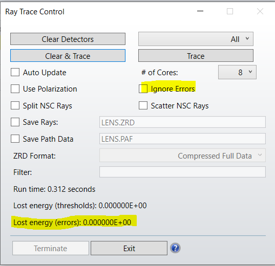
As @David.Nguyen said, ray trace errors are not always significant. In geometries like yours, they commonly occur when a ray hits the intersection between two surfaces, where the surface normal is ambiguous. The ray trace dialog reports the total energy lost to errors. If it is insignificant, you can check ignore errors and the errors won’t stop the trace.
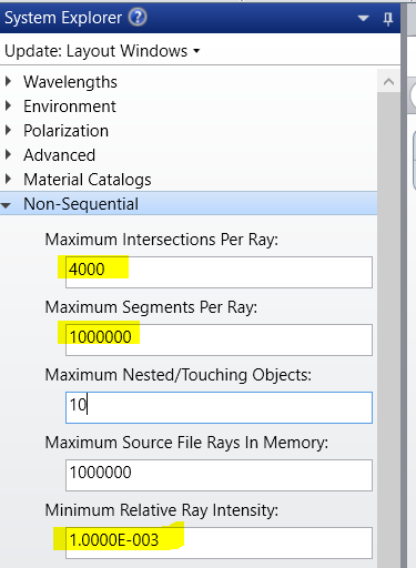
Regarding not enough segments errors, I suggest setting the number of segments and intersections to maximum, and then setting the minimum ray intensity to some reasonable value. That will prevent OS from tracing insignificant rays. You can see what’s lost in the Lost energy report in the ray trace dialog.
For working with coatings, you might also want scattering. There is a good article on that here.
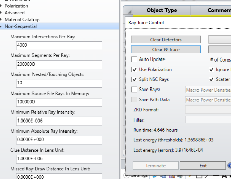
I suggest the issue lies in how you are defining the beam dump surfaces. With 1.3kW lost to rays each having 1e-6 or less, you have generated more than 1.3e9 rays each having less than the min energy. These rays are child rays which are geometrically increasing in number and decreasing in intensity according to the scattering, splitting, transmission, reflection, and absorption settings of the surface.
If you are using glass with surface coating set as default then splitting and scattering will both generate child rays, and repeated internal reflections will generate a lot of rays. If the surface is set to reflective, then only reflected scattering will generate child rays. But with 2 rays scattered plus the specular ray, that is 3x3x3x3x3x . . .rays. If the absorption is small, then there will still be a lot of child rays before the intensity of the new scatters drops below the minimum so that further ray generation stops.
I suggest looking at the number of rays generated and the absorption parameters. A starting point would be to (if using glass) make the coating surface reflective, and set the scatter fraction to 1.0 with 1 scattered ray. This will mean that the total rays being traced will not increase and you can see the result. You can see how many times a ray gets scattered before its intensity falls to below the min.
Note that you can also make the material MIRROR instead of glass and still coat it. That is done in the article to which I sent you a link.
If you are trying to measure the power intensity distribution on the surfaces, you could put detectors in front of them, internal to the dump, and set them to measure front only.
Thanks again for your detailed and well explained response.
I did that. I don’t know how to deal with the fact that yes - there are too many small rays that add up. I cannot ignore them. They’re necessary.
If I make the detector a “MIRROR” and coat it with say ideal “I.05”, the detector will still show ALL the energy (not just the 5%.).
I’m trying to measure the power absorbed by each surface after all of the bouncing around. Placing the detector in front of them will not help - it’ll show “all” of the incident power.
A few more comments. But please tell me if I’m over doing things!
The point of controlling the geometric increase in child rays is to limit the number of ray segments that are killed for low energy, while assuring coverage by increasing the number of analysis rays. The attached file models an integrating sphere. The walls have a coating that reflects 10% while absorbing 90%. Lambertian scattering is added with a varying number of child of rays scattered. The input to the sphere is a Source Ray. The Minimum Relative ray is 1e-15. So after 15 reflections a single ray will be killed.
Here is one ray scattering 15 times with one child produced at each scatter:
If we produce two child rays we get an extremely large number of rays, and many will have very low power. This is from only 1 ray launched. Edit: From a single ray launched we get 1.17e-13 W lost to thresholds.
However, if we produce only 1 child ray per scatter, we can increase the analysis rays to 1000 and get this. Edtt: From 1000 rays launched we get 6.36e-16 W lost to thresholds.
In the first case we have generated an enormous number of child rays having 1e-15 relative power. In the second case, we wind up with 1000 child rays each having 1e-15 relative power.
The point is to control the geometric expansion of ray segments, but get adequate statistics by the number of rays launched. For scattering, controlling the number of scattered rays produced does this. For splitting, we can use Simple Ray Splitting to do the same thing. In the case of 1000 rays launched and 1 child per scatter, we know we will have 1000 rays each having 15 child rays, and only 1000 rays will be killed for having relative power below 1e-15. So we are in control!
And regarding the detectors. If the detectors are set to Front Only and oriented to detect only rays which go through them to strike the dump surface -- not those reflecting back -- then you know the power striking the surface. If you also know the absorption, then I think you can calculate the absorbed power. There may be a more clever way to do this, perhaps with a bulk absorbing material.
We use 3 different kinds of cookies. You can choose which cookies you want to accept. We need basic cookies to make this site work, therefore these are the minimum you can select. Learn more about our cookies.