Hi , I want to design an imaging system where a beam is launched from a single mode fibre (core diameter 3 micron and NA=.12), goes through a collimating lens ( Thorlabs F671APC-405 - 405 nm, f = 4.02 mm, NA = 0.60 ) and  aspheric lens ( Thorlabs 354280-A - f = 18.4 mm, NA = 0.15, WD = 15.9 mm, Unmounted Aspheric Lens )is then focused on the image surface.

What would be the best way to simulate such a source in sequential mode and to find the resultant spot size on the image surface? To get the beam diameter of the collimated beam I have used two dummy surfaces ,and calculate the diameter value from semi-diameter parameters, is this process correct? If I use REAY operand at same surface I also get the some values, will it be the beam diameter value,which one is correct?  Here I uploaded my zemax file . 

I have not looked at your file yet, but you are going to want to use gaussian beam or physical optics tools for this. Check out the knowledgebase articles about modeling laser beams. https://support.zemax.com/hc/en-us/articles/1500005490261-How-to-model-laser-beam-propagation-in-OpticStudio-Part-1-Gaussian-beam-theory-and-ray-based-approach

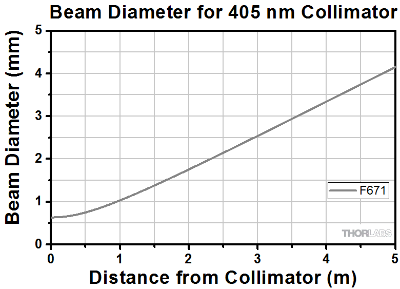
Thorlabs has this plot on their website which shows how fast the beam will grow when using the collimator you mention above. This beam diameter is calculated for a fiber with the same parameters you mention, and uses the GBPS (gaussian beam paraxial size) operand to calculate the size of the beam as it propagates out of the F671APC-405 collimator. 


Dear Sean

Many thanks for your reply.

To model the fiber as a source I have set the aperture type object space NA with the NA value .12 (fiber NA) and fields set to object height, maximum field is set to radius of fiber that is .0015.Is this correct way of defining the single mode fiber as a source object. 

Cheers

Sanjukta


I agree with @Sean Turner Sean and I’ll add my comments too. You’ll want to use the Gaussian Beam Propagation operands. The link that @Sean Turner uses makes the argument that the geometric ray based method is a good approximation and it is for the example that the knowledge base article describes; however, I can easily think of situations that would show the limitations of the geometric model and they are not that exotic.

I would suggest looking at Part-2 of that discussion that shows how to use the Gaussian Beam operands.

You can then use Physical Optics Propagation (POP) towards the end of the optimization to tune it slightly if par-axial is insufficient.

If you really want to see a cool implementation of geometric ray-tracing that will simulate Gaussian Beams, see this implementation of skew rays. I would only do this if I needed to make some very nice graphics where the geometric trace would be clearly misleading.


Reply