Hello!
I’m reverse-engineering a system, and have come across some problems.
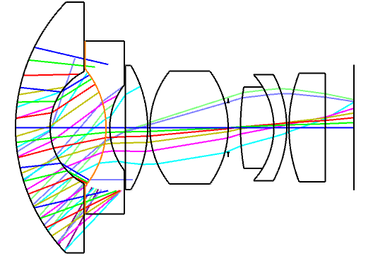
Why are the rays that are coming from the first surface stopping at the imaginary radius of surface 2 in the below image? The bottom part shows it more clearly.


Hello!
I’m reverse-engineering a system, and have come across some problems.
Why are the rays that are coming from the first surface stopping at the imaginary radius of surface 2 in the below image? The bottom part shows it more clearly.
Best answer by Christian Zimmermann
Hello Oscar,
unfortunately I don’t see the Lens Data Editor. Nevertheless I would say it has got to do with the “Clear Semi-Diamter” vs. “Mechanical Semi-Diameter” settings. Did you apply a certain amount of “Chip-Zone” to the surfaces? How about the vignetting settings shown in Field Data Editor? Have you got “Float-by-Stop-Size” or Image Space F/# defined as aperture of the lens?
Kind regards,
Christian
Enter your E-mail address. We'll send you an e-mail with instructions to reset your password.
Do not provide any information or data that is restricted by applicable law, including by the People’s Republic of China’s Cybersecurity and Data Security Laws ( e.g., Important Data, National Core Data, etc.).
不要提供任何受适用法律,包括中华人民共和国的网络安全和数据安全法限制的信息或数据(如重要数据、国家核心数据等)。

