Solved

An issue with Physical Optics Propagation using .zbf exported from Lumerical 3D-FDTD

  • 29 September 2022
  • 2 replies
  • 347 views

Hi everyone,


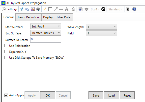
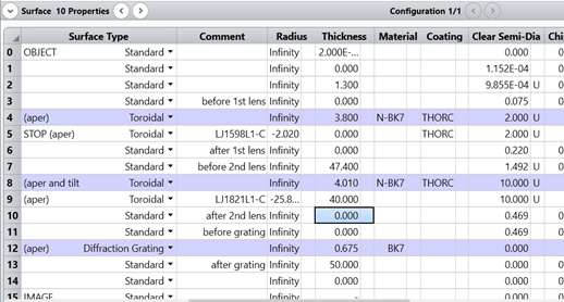
I am trying to analyze the field profile at different surfaces in sequential mode using POP, in a system with two commercial cylindrical lenses where the input source is a .zbf file exported from Lumerical 3D-FDTD. The .zbf file corresponds to a beam coming out of an end-fire waveguide (phased) array, captured 100 μm away from the waveguides’ facet. Both .zbf and zemax setup files are attached here.


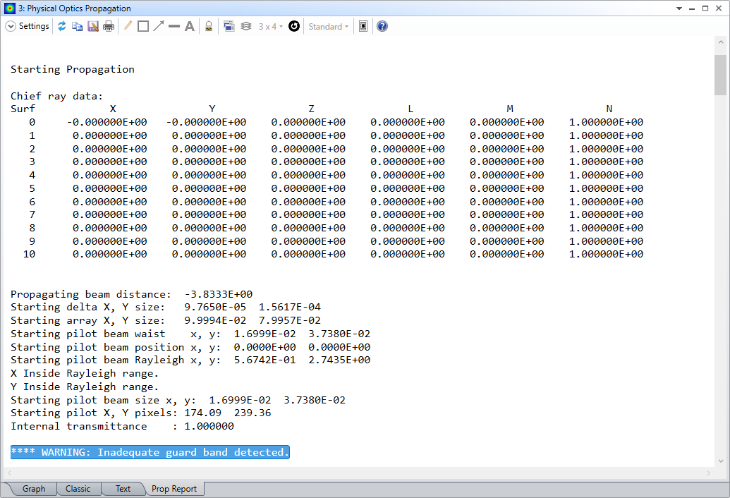
The main issue I am facing is at producing a reasonable image of the beam at surfaces before and after the two lenses. While the source is inserted correctly in zemax, in the Physical Optics Propagation tab the beam seems to not be formed correctly at the desired surfaces before and after the lenses, and quite often artifact fields are observed. I have been experimenting with the Physical Optics Properties of the surfaces in the Lens Data tab by choosing various different X-, Y- Sampling and X-, Y- Width combinations. However, until now I do not have an indication that the images displayed at the POP results window are valid.


For instance, after the 2nd lens at surface 10, a different irradiance field is displayed when the POP settings of surface 7 are checked on or off, as well as for different XY sampling:

Various POP results at surface 10.

In addition, surfaces 6 and 7 do not display any result at the POP window (artifacts).

The input .zbf source with 1.6μm wavelength is depicted below, featuring a main beam as well as sidelobes that are expected to appear in POP analysis. The optical setup is also shown.

Input source (left) and the optical setup (right).
Lens data sheet

Could you please provide assistance on how to tackle this issue and correct any error in order to successfully propagate the beam? The scope of this study is to analyze propagated beams with different wavelengths after every lens and ultimately after a transmissive diffraction grating.


Thank you very much in advance, any help is really appreciated.


Kind regards,
George

icon

Best answer by Csilla Timar-Fulep 30 September 2022, 18:14

View original

2 replies

Userlevel 5
Badge +2

Hi George,

Thanks for your post here on the Community Forums.
Also, thanks for sharing your sample files. I have taken a look at these files and have a couple of comments.

First of all, taking a look at the Prop Report tab of the POP analysis, there is warning right after the ZBF beam import saying **** WARNING: Inadequate guard band detected:

 This means that the guard band around your beam is not enough for the POP propagation. We have to keep in mind that in general the ideal sampling and guard band for FDTD and POP are not the same. So, you might want to add a guard band around your beam to make sure it complies with the requirements of POP. To learn more about the sampling advice in POP, please take a look at the Help files at:
The Analyze Tab (sequential ui mode) > Laser and Fibers Group > About Physical Optics Propagation > Comments about Point Spacing and Sampling

Also, may I ask if there is any specific reason for using the Entrance Pupil as the beam Start Surface in POP?
I would rather suggest to use a specific surface from the Lens Data Editor. You may change this under the General Settings:


Finally, is there a  reason why you captured the beam data in FDTD 100 μm away from the waveguides’ facet? Maybe you can capture it closer to or right after the facet, and pass that data to OpticStudio.

In general, you may find more information about how to pass data between Lumerical and OpticStudio in this knowledgebase article and webinar below:
How to convert from Lumerical simulations to OpticStudio and back – Knowledgebase (zemax.com)
[Webinar] Zemax and Lumerical: Part 1 - From Nano-scale to Macro-scale Optics and Back | Zemax Community

I would also suggest to take a look at the following knowledgebase articles about how to set up POP simulations, and how to troubleshoot any errors with those:
Exploring Physical Optics Propagation (POP) in OpticStudio – Knowledgebase (zemax.com)
Using Physical Optics Propagation (POP), Part 1: Inspecting the beams – Knowledgebase (zemax.com)

In general, of course it can make a difference if you switch on or off the settings in the Physical Optics tab at different surfaces in the Lens Data Editor. As a first step, I would suggest to try to use the default settings, i.e. do not overwrite or re-sample, inspect the Prop Report of POP and check for any warnings or error messages. Usually, you do not need to alter from the default if there are no errors.
You may find more details about how the Physical Optics properties of the individual surfaces modify the beam propagation here:
The Setup Tab > Editors Group (Setup Tab) > Lens Data Editor > Surface Properties > Physical Optics

Finally, you may find more details and suggestions for use for POP in the Help files at:
The Analyze Tab (sequential ui mode) > Laser and Fibers Group > About Physical Optics Propagation

I hope this helps, but if you have any further questions, please ask.

Best,
Csilla

Thank you very much for the reply!

Reply