Solved

Adding boundary conditions to the merit function

  • 25 July 2022
  • 3 replies
  • 574 views

Userlevel 6
Badge +4

I have both a question and possibly a suggestion for a new feature.

I have often wanted to design a lens with a specific design form.  It is quite easy to use OpticStudio to craft a plausible starting point for the design. Just set up the fields and aperture, open up a layout, and start adding components to the to the lens data editor so as to produce the form and guide the chief and marginal rays through in about the right way.

The next step is to optimize the lens to get optimal values for radii and thicknesses, and perhaps to identify the best glasses by glass substitution. That’s where the problems start. I know the design form I want, but the optimization routines don’t respect my wishes. Hammer and Global Search, and even just a straight Optimize, will lunge about frantically. They often come up with a good design, just not what I’m looking for.

With a lot of effort, the merit function can be crafted to constrain the design to respect my wishes. Often this means adding bilateral boundaries on every thickness and curvature. I would like to know of an easy way to accomplish this. It could likely be done with a macro, or even in the API, but that is also a lot of work. Any suggestions?

Absent a nice method I have overlooked, my suggestion is this:

Could we perhaps have a Wizard for the merit function that would add boundary conditions based on what it finds in the Lens Data Editor? The wizard might accept a set of criteria, like percent or magnitude limits for thicknesses and curvatures, and add the operands to the merit function necessary to enforce the boundaries.

icon

Best answer by Mark.Nicholson 26 July 2022, 04:45

View original

3 replies

Userlevel 7
Badge +3

Hey David,

I’ve experienced the same thing with my Basic Shapes of Imaging Systems series. The optimizer reduces the merit function: that’s all it can do. It doesn’t know a Cooke triplet from a Tessar from a double Gauss.

I think this is A Good Thing. Many of the classic designs resulted from tracing a handful of rays, and they are not necessarily optimal when you can trace many rays. In particular I have noticed a tendency to add a field flattener to almost any design with sufficient field unless you constrain the design to have a large back focal length.

The constraint for large back focal lengths in imaging systems was of course to accommodate the shutter and viewfinder of classic photographic lenses. Without that constraint, it’s hard to get the classic shapes, and you’ll almost always get a lens close to the image surface as this controls field curvature so well.

  • Mark


Userlevel 6
Badge +4

I think that’s a good point, Mark. It’s probably not good to assume a classic form is the best we can do. 

Userlevel 6
Badge +4

I have to admit that most of the time when I want to constrain a design to a particular form is when I am trying to figure out what someone else has done.

I recently came across a very low cost 50mm F2 lens designed for the new mirrorless cameras.  (I have one on order for my Nikon Z6ii.) The vendor literature on the lens provided the usual advertising graphics. An online review of the lens says that it has acceptable image quality, except for being a bit soft wide open, but suffers from both flare and veiling glare when a bright source is anywhere near the image area.

I thought I might like to investigate the design, but of course I do not have a prescription. What I have is this from the vendors site:

And this from an online review:


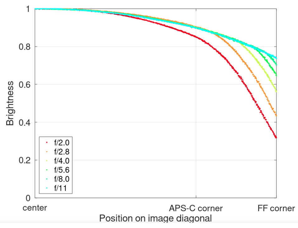
So what I have is a basic layout without dimensions, and evidence that significant vignetting is being used to reduce aberrations at the edge of the field. We know the lens is 50mm and F2, and it’s for a full frame camera so we can assume the extreme field in image space is at about 21mm. Since it’s for a mirrorless camera the back focal distance is likely about 20mm. Given the price and reasonably good bokeh it seems unlikely there is an aspheric element.

I crafted a rough layout for this in OpticStudio:


This starting point is 70mm F3.8, and needs to become 50mm F2. It also needs to achieve good imaging. What I am asking then is this:

Is there a good way to use OpticStudio to optimize this lens by determining curvatures, thicknesses, and glass types while preserving the form of the design such that the final layout still looks like the vendor’s illustration.

I stress that I am NOT trying to reverse engineer this lens for any nefarious purpose. This is just an exercise. However, if this makes the moderator’s uncomfortable, please feel free to delete this post!

I have attached my “starting point” as a ZAR.


Reply