


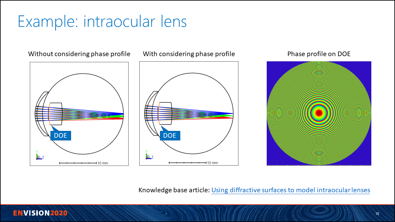
Sometimes we might have some phase profile from a DOE lens or metalens and want to simulate it in OpticStudio. In this case, we can simply use the sequential surface 'Grid Phase' to import and simulate the data.
However, care should actually be taken in this case. In short, if the phase profile comes from FDTD, BPM, or similar calculation, the data should only be used with POP but not ray-tracing. Otherwise the calculated result can be incorrect. Note here we are mainly focusing on importing a phase profile for DOE lens or metalens.
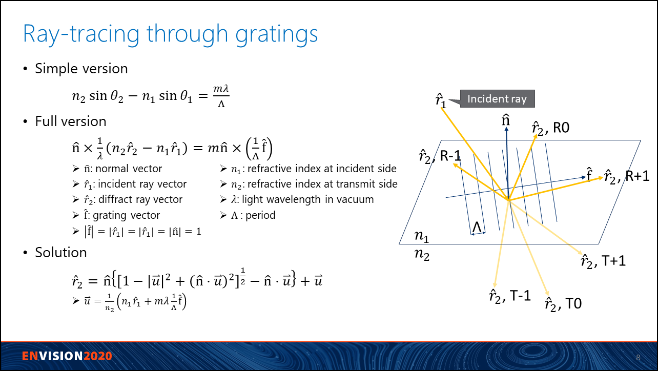
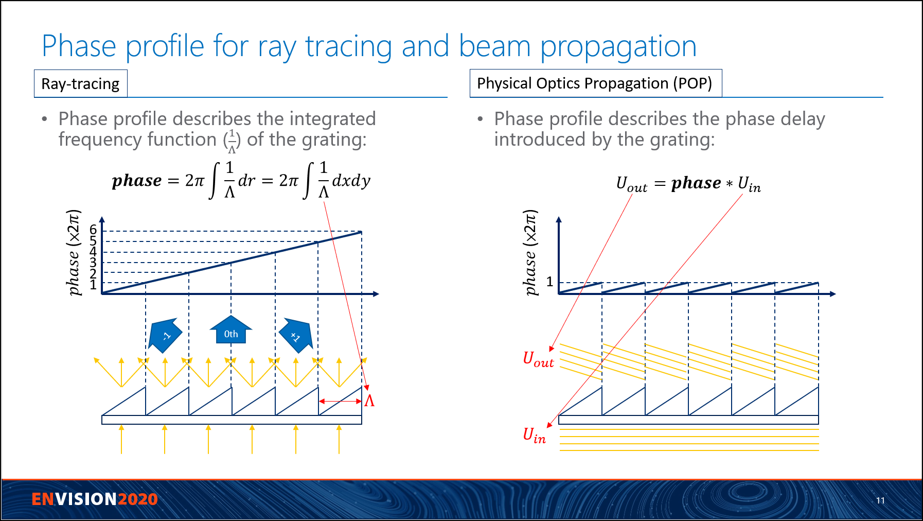
To understand more details, we can first look at the following two slides to understand how the diffraction ray-tracing is calculated. The first slide shows how a ray is diffracted by a grating. It's important to know ray-tracing through a DOE or grating is calculated based on the 'frequency' or 'period', but not anything about the real structure.
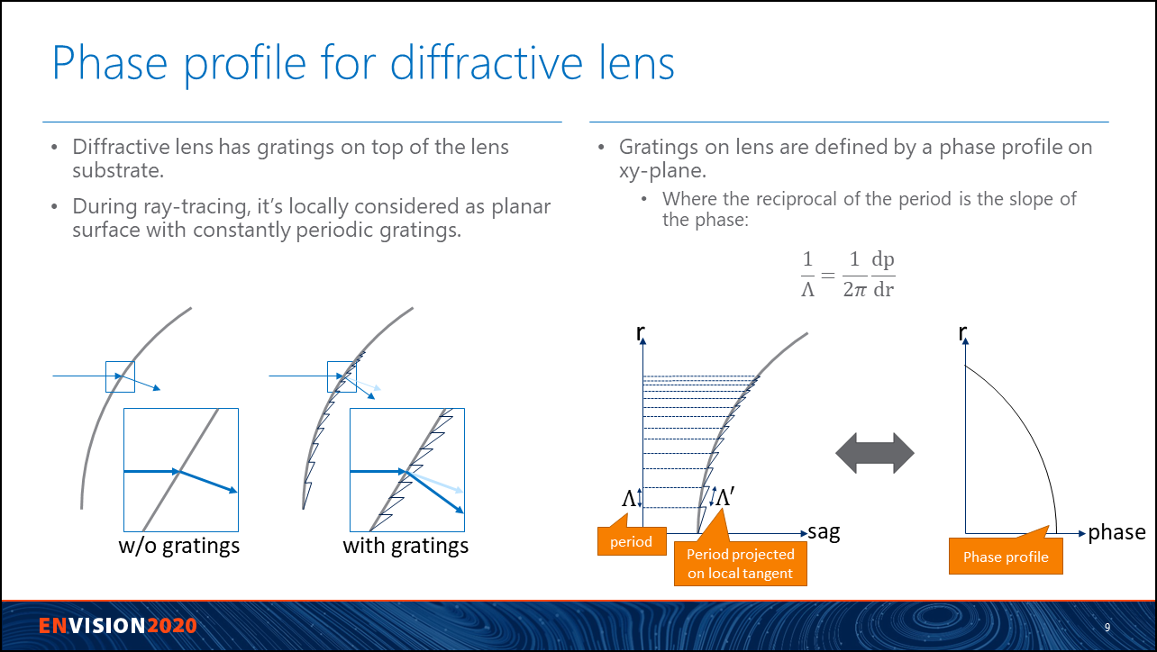
In the second slide, it further explains that the phase profile under this methematical picture is simply an integral of the frequency, or reciprocal of period. Again it's important to notice the phase profile is not related to the detialed structure here. The phase profile is always same, no matter what the detail structure is, as long as the period of the grating is not changed. Let's call this phase profile as 'phase profile for ray-tracing'.
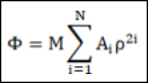
In OpticStudio, the DOE can be designed using the phase. One of the most common surface to use is the Binary 2. In Binary 2, a phase profile is defined as below. When a ray hit this surface, we take derivative of this phase and diffract it follwoing the diffraction equation as described in previous slides.
So far so good. This is how phase profile means under the picture of geometricl ray-tracing. The phase profile simply only describes how the period/frequency of a grating distrubuted over the DOE lens/metalens. There is nothing about the fine structure at each period in the grating. No matter it's a blazed, step, or binary gratings, the phase profile will be same as long as the period doesn't change.
OK, now let's try to see what a phase profile may mean for a diffractive propagation. In OpticStudio, that is the Physical Optics Propagation (POP). In POP, there is no rays. Light is propagated as a beam, 2D array of complex data. When it see a phase profile, it simply multiply it with the input beam and get the output beam.
The phase profile used for POP can be very different to phase profile for ray-tracing. Firstly, let's look at the following case with a blazed grating. In this case, the phase of blaze grating for POP is similar to that for ray-tracing, except it takes modulo of 2pi.
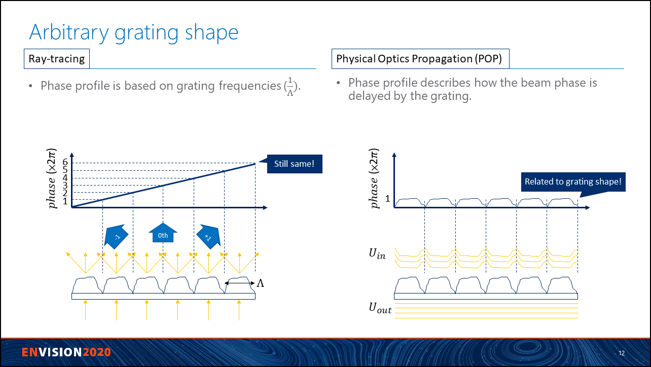
However, if we change the grating shape, then it's clear the phase profiles for ray-tracing and POP are different. Usually the phase profile is calculated from FDTD, BPM, or other similar nano-optics software, as shown in the right side in following picture. If we use this phase profile to simulate for ray-tracing, rays will use its phase slope and be diffracted to wrong direction.
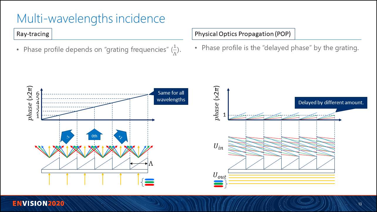
The following slide shows a common mistake users may make. That is, phase profiles for different wavelength are generated in nano-optics software, as shown at right side, and then used for ray-tracing. It's important to know the phase profile at right side should not be used in ray-tracing. For ray-tracing, the phase profile is always only linked to the period, as shown at left side of the picture. No matter what wavelength of the light is incident, the phase profile used for ray-tracing is always same, as long as the period is same. If we generate phase profile from nano optics software for different wavelength and import it into OpticStudio, then system should be verified by POP.
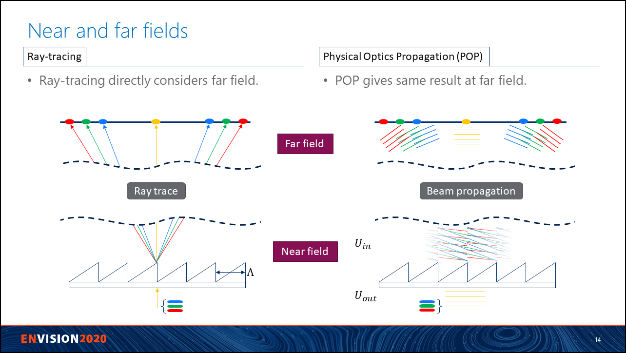
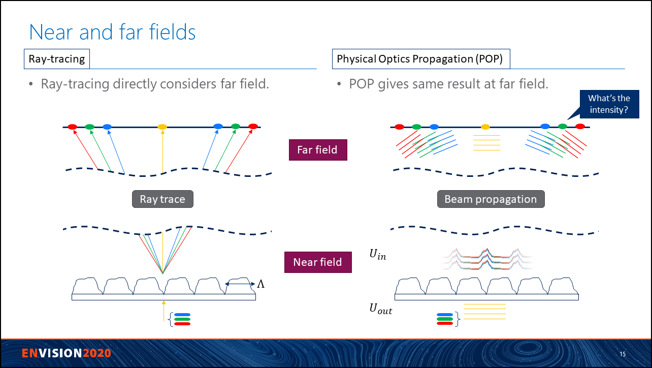
Another view point to understand this discrepancy between diffraction propagation and ray-tracing is by looking at the far field.
As in following slide, left side shows rays are diffracted following phase profile for ray-tracing. Different wavelength is diffracted into different direction.
At right side, we see different incident plane wave is first converted into corresponded wavefront. By looking at near field, you may feel the blue light will be diffracted to farer point that red light. However, at far field, you can actually see an opposite result. This is because the diffraction direction is actually mainly affected by the period of the grating, not the detailed micro structure. What the micro structure affected is the 'efficiency' of each diffraction order.
It's even clearer if we look at the following slide, where I replace the grating with an arbitrary shape for each period. The near field wavefront of each wavelength are very arbitrary, but they will still go to same direction determined by the given period.
From this viewpoint, we can actually say the ray-tracing only consider far field. And that is why it's only related to period but not local fine structure.
In conclusion, the phase profile generated by nano optics software should not be directly used with ray-tracing. The phase profile for ray-tracing should simply describes the distribution of the period or frequency of the DOE lens/metalens.