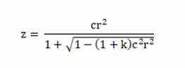
I am trying to develop a UDS (User Defined Surface) DLL and have been reading the excellent articles in knowledge base about this. Taking as the starting point the “us_stand.c” code for the standard surface (available in the folder /Zemax/DLL/Surfaces), I understand that Zemax provides an intercept point to the tangent plane (x0, y0, z=0) and direction cosines (l0, m0, n0) for the ray at that point. Then the real ray trace is performed in case 5 and for complicated surfaces there is no analytical solution for the ray intercept point on the surface. Hence an iterative solution is needed.
What I am struggling to understand is: how do those equations in case 5 work? I thought that there would be no analytical solution to find the ray intercept point with the standard surface. However, the equations in case 5 seem to be quite simple, although I was not able to derive them.
Therefore, my questions are:
- Is the algorithm in case 5 of “us_stand.c” implementing a closed-form analytical solution, as opposed to an iterative algorithm?
- How were those equations derived? For example, what is the meaning of ‘a’, ‘b’, ‘c’, ‘rad’, etc in case 5? Are they defined and explained somewhere?
- Do you think it is possible to use these equations to super-impose a radially symmetric structure on the standard surface and still obtain an analytical solution (if that is what we have in case 5)?
Basically, I have an equation that I want to add to the equation of the standard surface. My understanding is that even in the standard surface case we should apply iterative methods, but it seems that the Zemax solution is a lot more elegant than that. Any comment and help with this will be greatly appreciated!
Thanks!