I have surfaces near the focus of an aberrated system and I’m seeing that the Clear Semi-Diameter is being automatically set much smaller than the actual beam size. I know that this is because the surface is in a caustic region and I can set a fixed value rather than leave it as automatic. I’d like to have another option, to size it based on something other than the marginal ray height at the surface. What options do I have?
Solved
ZPL Macro Solve to size the Clear Semi-Diameter
 +1
+1Best answer by Kevin Scales
You are quite correct about the reasoning behind the small Clear Semi-Diameter. The automatic setting is based on the marginal rays for the various fields, with the assumption that the marginal rays are further from the optic axis than any others. In a caustic, a region defined by marginal rays not being furthest out because the focal length is not constant for an aberrated system, this will not provide the correct answer.
We do have additional options, and one of them is to use the ZPL Macro solve rather than the Automatic, Fixed, Pickup, or Maximum solve types. Here is a simple macro that loops through fifty rays over Y for each field and measures the largest Y coordinate for use in the Clear Semi-Diameter. To apply the solve, click on the box to the right of the Clear Semi-Diameter cell in the Lens Data Editor and pick ZPL Macro, then provide the name of the macro, which for this example is called ‘Applied-Semi-Diameter.ZPL’ and is found in the Zemax\Macros folder.
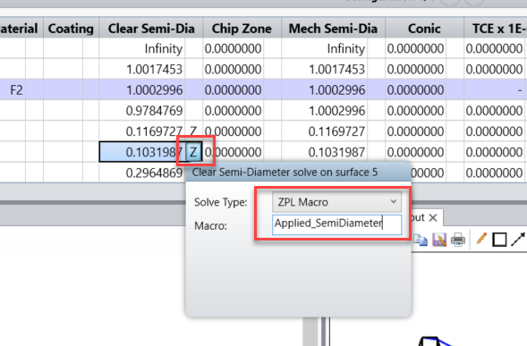
The macro, titled Applied_SemiDiameter, is attached here and looks like this:
numfields = nfld()
maxfield = 0
for field, 1, numfields, 1
if abso(fldy(field)) > abso(maxfield)
maxfield = fldy(field)
endif
next
surface = soso(0)
AppliedSD = 0
for h, 1, numfields, 1
if abso(maxfield) < .0001
hy = 0
else
hy = fldy(h)/abso(maxfield)
endif
for py, -1, 1, 0.04
raytrace 0, hy, 0, py
if abso(rayy(surface)) > AppliedSD
AppliedSD = abso(rayy(surface))
endif
next
next
solvereturn AppliedSD
The first block loops over the defined fields to find the absolute value of the largest measured along Y. Then the next block loops over each field and computes its Hy value (the normalized Y portion of the Hx,Hy normalized field coordinates). For fifty-one values of the normalized pupil coordinates in Y, Py = 1 to Py = -1 in steps of 0.04, a single ray is traced to the calling surface and the one with the largest absolute value in the Y-coordinate is set as the return value.
That’s it. Just apply this macro to the Solve on the Clear Semi-Diameter and observe that an accurate and reasonable value is now placed in the cell parameter. See the attached file, CausticSemidiameter, for an example of this. Surface 4 has the macro solve applied already. Surface 5 is ready to receive one.
This example is pretty simple, but if you want to make changes or additions, the macro is easily modified. You could check for X coordinate effects or other fields that are not all defined by Y. You could pad the resulting returned value by an additive or multiplicative factor. You can change the resolution to finding more or fewer than fifty-one rays. The existing framework allows for all of these options or more.
Enter your E-mail address. We'll send you an e-mail with instructions to reset your password.
Need more help?
To Chinese users:
Do not provide any information or data that is restricted by applicable law, including by the People’s Republic of China’s Cybersecurity and Data Security Laws ( e.g., Important Data, National Core Data, etc.).
不要提供任何受适用法律,包括中华人民共和国的网络安全和数据安全法限制的信息或数据(如重要数据、国家核心数据等)。